
Printer system, printer control method, and recording medium

a printing system and printer technology, applied in the field of printing systems, can solve the problems of long time and delay in printing completion, and achieve the effect of quick completion of printing operation

Active Publication Date: 2007-02-20
SEIKO EPSON CORP
View PDF23 Cites 55 Cited by
  • Summary
  • Abstract
  • Description
  • Claims
  • Application Information

AI Technical Summary

Benefits of technology

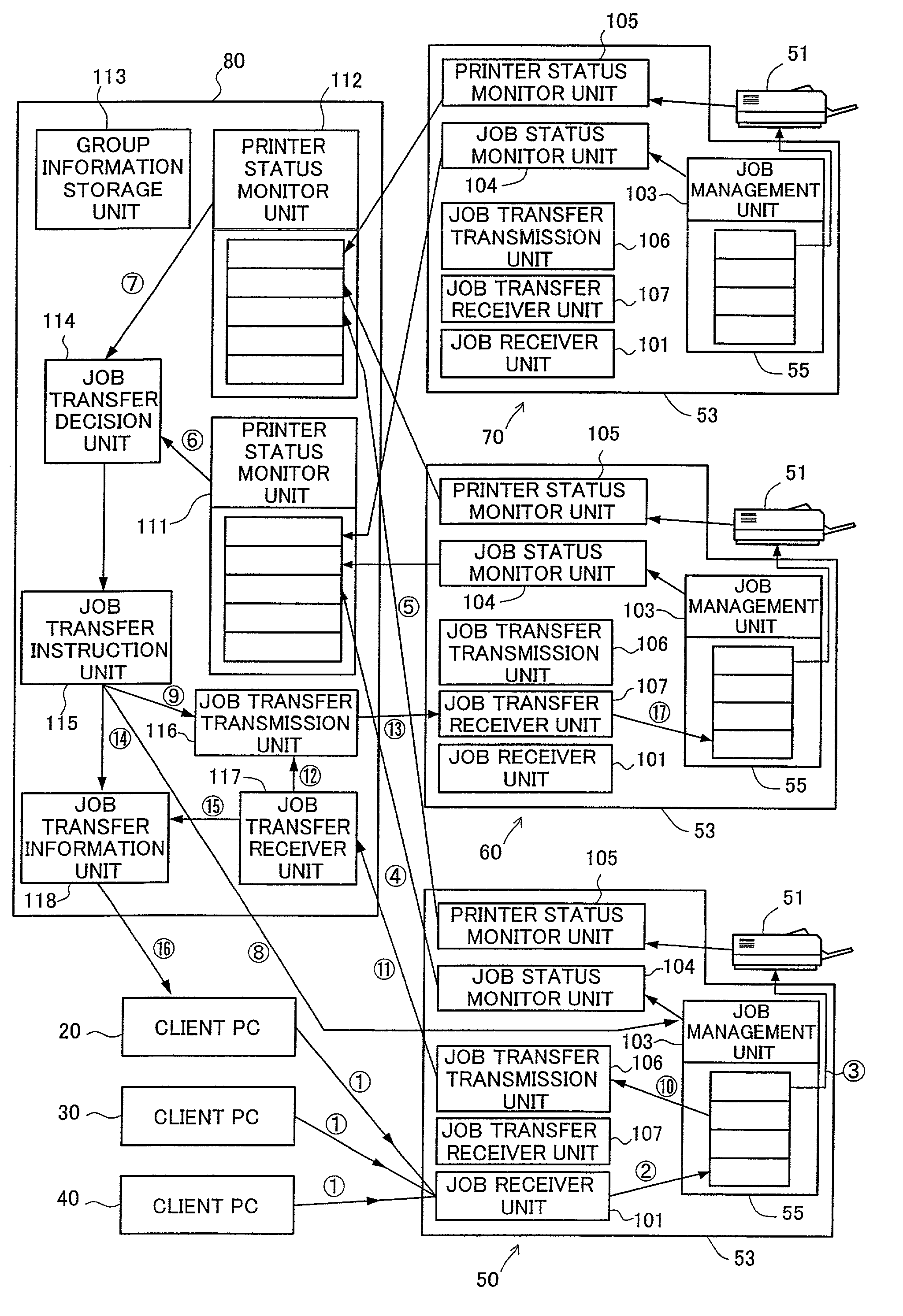
[0008]The at least one print job stored in the buffer of the source printing apparatus can thus be transferred automatically to another printing apparatus, which is included in the preset range of printing apparatuses among the plurality of printing apparatuses, according to the requirements. When there is a significant delay of printing operation in response to a print job in a certain printing apparatus, this arrangement enables the printing operation to be carried out by another available printing apparatus. This desirably ensures quick completion of the printing operation.
[0051]The first recording medium and the second recording medium of the present invention exert the same functions and the effects as those of the first printing system and the second printing system discussed above. When there is a delay of printing operation in response to a print job in a certain printer, the arrangement enables quick completion of the printing operation.

Problems solved by technology

In the event that a number of print jobs output from a plurality of client personal computers are sent to one printer in a concentrated manner, the prior art technique requires a long time to start printing with regard to a print job at the end of the long queue and thus delays completion of printing.

Method used


Image

  • Printer system, printer control method, and recording medium
  • Printer system, printer control method, and recording medium
  • Printer system, printer control method, and recording medium

Examples


first embodiment

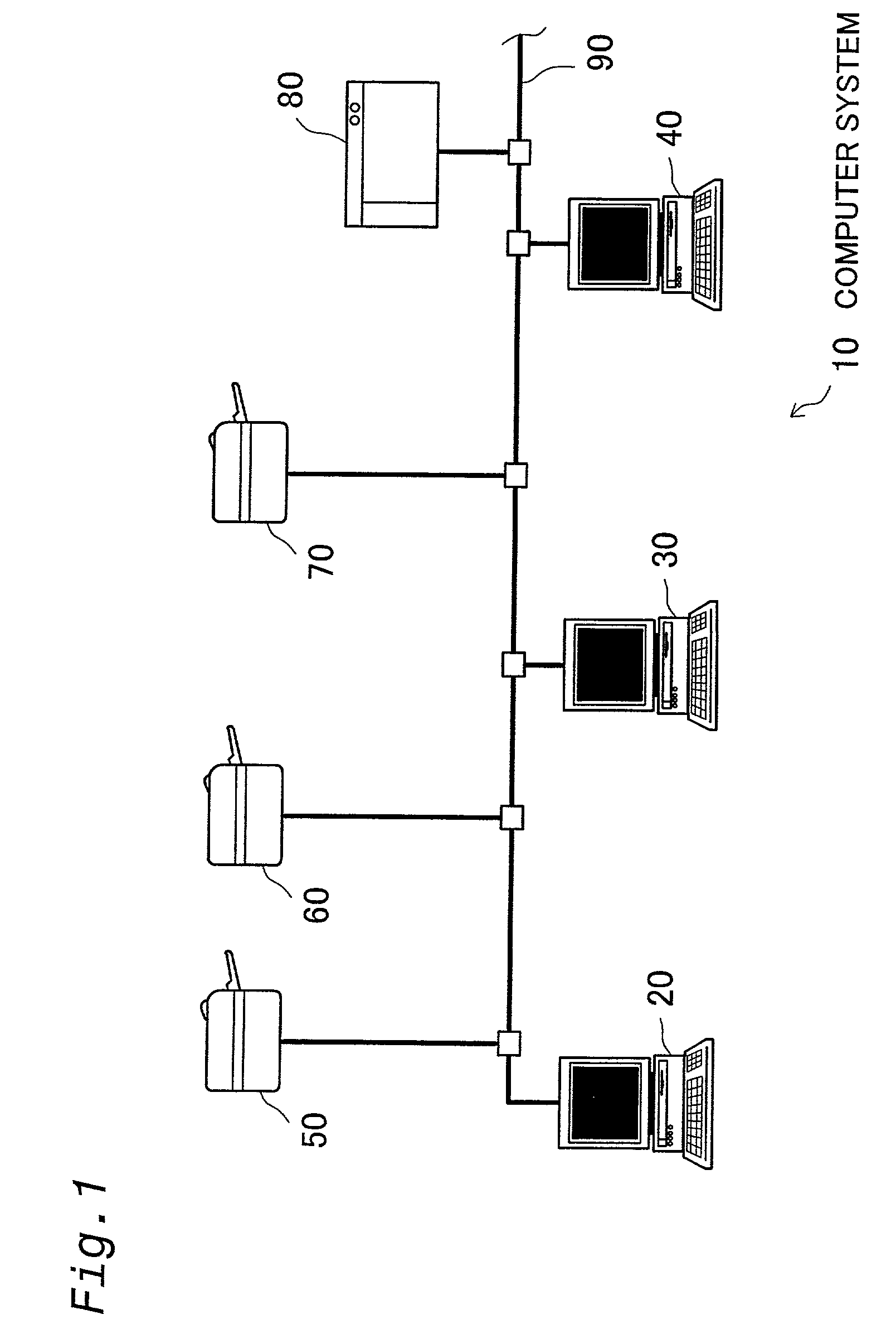
[0067]In order to further clarify the configurations, functions, features, and advantages of the present invention, some modes of carrying out the present invention are discussed below as preferred embodiments. FIG. 1 schematically illustrates the configuration of a computer system in the present invention.

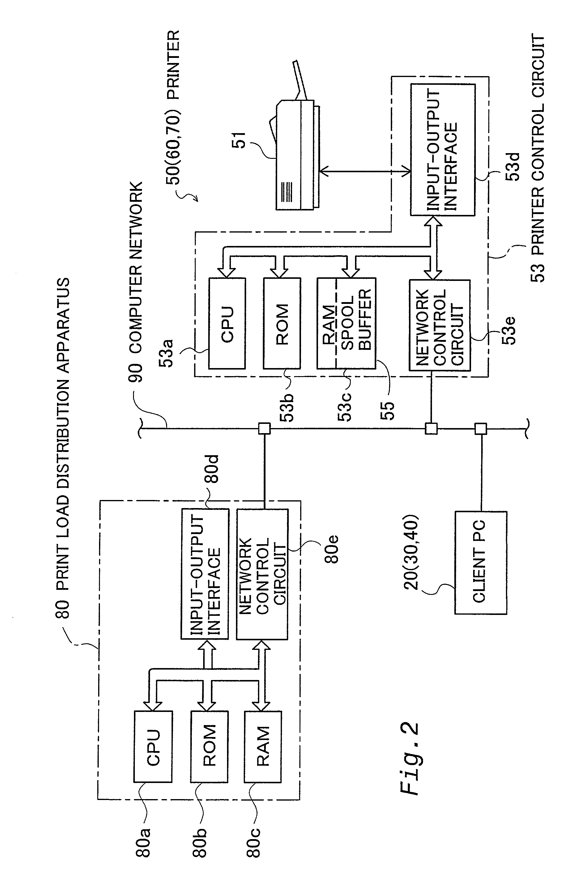
[0068]As illustrated in FIG. 1, a computer system 10 of this embodiment includes a plurality of (three in the illustration of FIG. 1) personal computers (hereinafter referred to as client PCs) 20, 30, and 40 that respectively output print jobs, a plurality of (three in the illustration of FIG. 1) printers 50, 60, and 70 that carry out printing operations in response to the print jobs, and a print load distribution apparatus 80 that distribute the print load of the printers 50 to 70, which are mutually connected via a computer network 90 constructed as a Local Area Network (LAN). The computer network 90 is, however, not restricted to the LAN but may be any of diverse networks, for ...

second embodiment

[0123]Among a diversity of processing routines described in such computer programs, processing routines characteristic of the second embodiment are discussed below. The CPU in the print load distribution apparatus 580A (580B) executes an available printer specification and monitor routine to actualize the available printer specification unit 650 and the available printer monitor unit 651, while executing a communication control routine to actualize the communication control unit 652. FIG. 9 is a flowchart showing the available printer specification and monitor routine. This routine is iteratively carried out at preset time intervals.

[0124]When the program enters the routine, the CPU in the print load distribution apparatus 580A (580B) carries out the series of processing at steps S700, S710, and S720, which is identical with the processing of steps S400, S410, and S420 of the first embodiment. The CPU subsequently specifies available printers having sufficiently short queues of prin...

third embodiment

[0141]In each printer control circuit 953 of printers 950, 960, and 970 included in the computer system 900 of the third embodiment, the job receiver unit 101 receives account attribute information in the process of receiving a print job from any of the client PCs 20, 30, and 40. An account authentication decision unit 981 carries out an account authentication decision process, based on the input account attribute information. The authentication decision process determines whether or not the print job has authority to use each of the printers 950, 960, and 970 included in the computer system 900, based on the presence or absence of the account in an account list provided in advance for the printers 950, 960, and 970. When it is determined that no authority is given, a transmission prohibition unit 982 prohibits the job receiver unit 101 from receiving the print job corresponding to the account.

[0142]The account list is stored in a non-illustrated account management device. The accou...


PUM


Abstract

The technique of the present invention enables quick completion of printing operations even when a large number of print jobs are concentrated on one printer. A print load distribution apparatus 80 monitors the job status in a buffer 55 and the error status of a printing mechanism 51 in a range of preset three computers 50, 60, and 70 among a plurality of computers connected to a computer network. When a number of print jobs are concentrated on one printer (for example, the printer 50) or when one printer (50) is in the error status, the print load distribution apparatus 80 takes in at least one print job stored in the spooling buffer 55 of the corresponding printer (50) and transfers the at least one print job to another printer (60 or 70) in the range of preset three computers 50, 60, and 70.

Description

TECHNICAL FIELD[0001]The present invention relates to a printing system where a plurality of printing apparatuses, each including a printing mechanism and a spool buffer, and at least one information processing apparatus outputting a print job are mutually connected. The present invention also pertains to a printing control method related to the printing system, as well as a recording medium.BACKGROUND ART[0002]A known technique of sharing printers mutually connects a plurality of client personal computers and a plurality of printers via a network. One example of such configuration provides each printer with an internal or external print server. This allows connection of the respective printers to the network via their print servers. Each of the print servers supports the spool function to process print jobs output from multiple client personal computers. The print server takes advantage of the spool function and successively outputs the stored print jobs to the corresponding printe...

Claims


Application Information

Patent Timeline
IPC IPC(8): G06F15/00G06K1/00G06F3/12
CPCG06F3/1207G06F3/1212G06F3/1285G06F3/1261G06F3/1259
Inventor GASSHO, KAZUHITOSEKIZAWA, HIROAKITSURUMAKI, HARUO
Owner SEIKO EPSON CORP
Learn More