
Band edge amplitude reduction system and method

a technology of amplitude reduction and band edge, applied in the field of wireless communication, can solve the problems of overloading the radio receiver circuitry in the base station, massive spurious response in the digital domain, etc., and achieve the effect of preventing interference with or the overload of the receiver and improving the attenuation of the signal

Inactive Publication Date: 2007-02-20
ALCATEL-LUCENT USA INC +1
View PDF14 Cites 32 Cited by
  • Summary
  • Abstract
  • Description
  • Claims
  • Application Information

AI Technical Summary

Benefits of technology

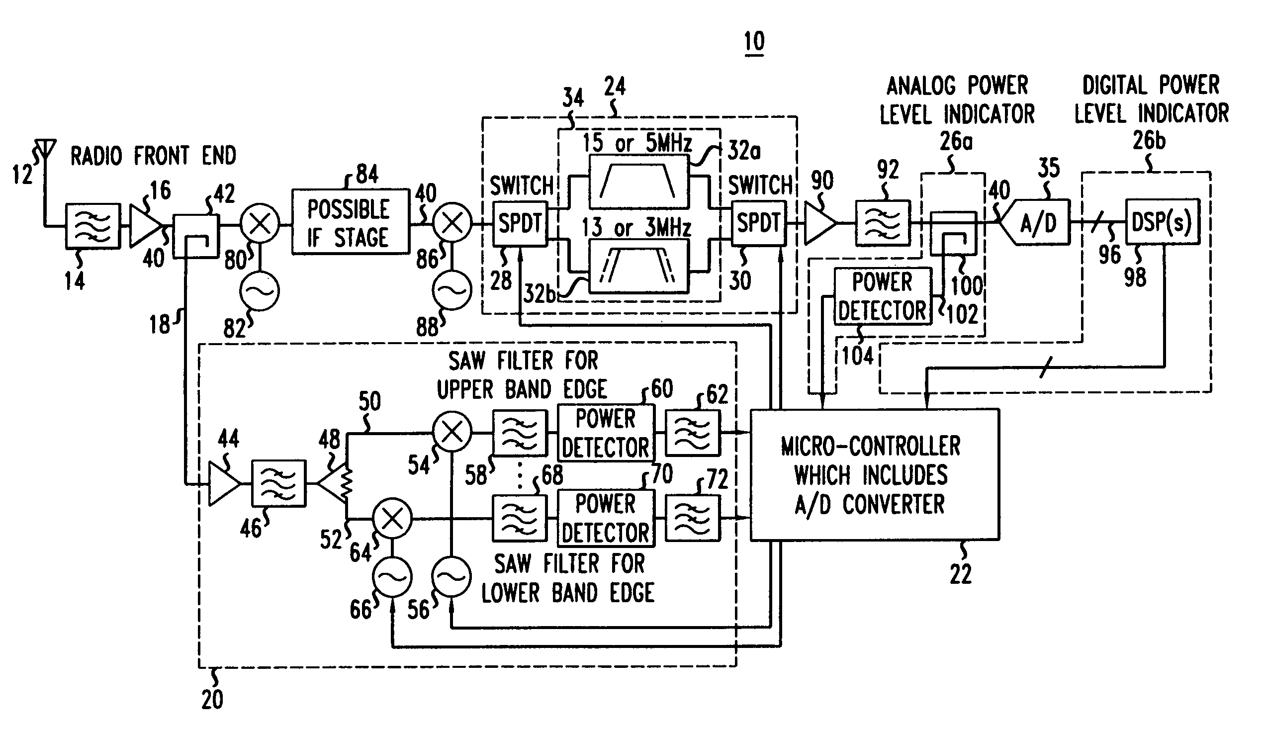
The present invention is a system that reduces the amplitude of signals at the edges of a receiver's operating band. It does this by measuring the power level of signals adjacent to the receiver's band and changing the filtering characteristics of the receiver to attenuate the signals from those adjacent bands. This prevents interference and overload of the receiver from signals outside its operating band and not under its power control. Overall, the system improves the quality of the received signals.

Problems solved by technology

Since frequency bands of adjacent cells and / or adjacent wireless communications systems are not under the power control of the same base station, there is a possibility that one or more signals / carriers from another cell that are close to the operating frequency band of a base station might be too strong in power and overload the radio receiver circuitry in the base station.
The sudden change (or sudden stop / clipping) in binary output pattern from the A / D converter, which digitizes and tracks the analog input signal, is called a discontinuity and results in a massive spurious response in the digital domain (when a Fourier transform is taken of the supposed analog input signal with a sudden clipping of the amplitude).

Method used


Image

  • Band edge amplitude reduction system and method
  • Band edge amplitude reduction system and method
  • Band edge amplitude reduction system and method

Examples


Embodiment Construction

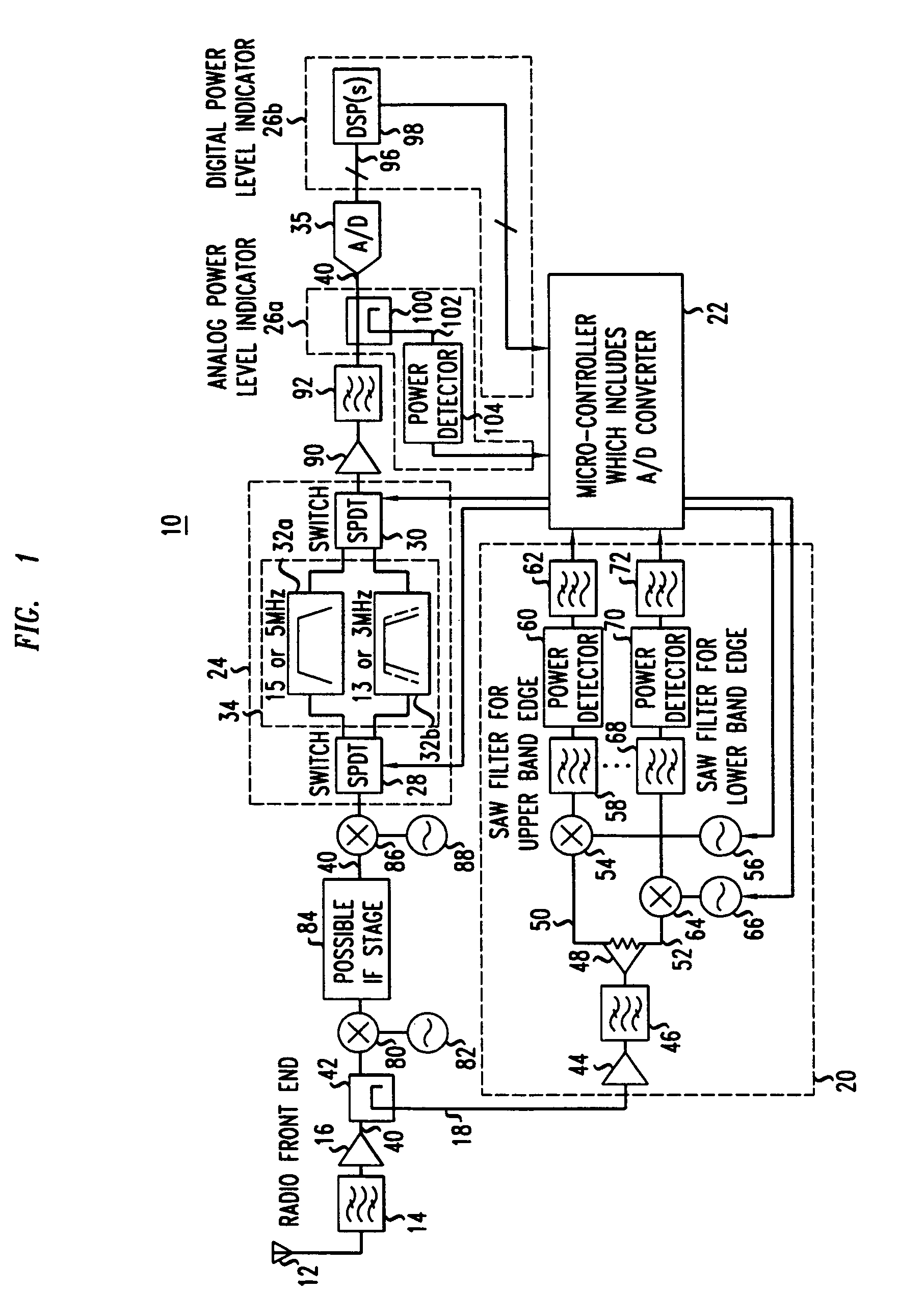
[0013]Illustrative embodiments of a receiver system using the band edge power reduction circuitry according to the principles of the present invention is described below. With particular reference to FIG. 1, a receiver 10 includes an antenna(s) 12 which receives radio frequency (RF) analog signals which are filtered by a RF bandpass filter 14 to produce an operating frequency band for the receiver 10. The output of the RF filter 14 is provided to an amplifier 16, such as a low noise amplifier for amplification. The radio front-end is comprised of at least the antenna 12, the RF filter 14 and the amplifier 16. A replica of the operating frequency band is provided to a band edge detection path 18 for detection by band edge power detector circuitry 20. The band edge power detection circuitry 20 measures at least one amplitude, such as power level, for a bandwidth(s) adjacent to or at the edge(s) relative to the operating frequency band and / or from signals not under the control of the r...


PUM


Abstract

A band edge amplitude reduction system changes the filtering characteristics of a receiver based on the amplitude of signal(s) adjacent to an edge of the operating band of the receiver and / or of signals not under the power control of the receiver. For example, the receiver measures the power level over a bandwidth at the band edges of the operating band of the receiver. If the signals adjacent to the operating band are strong enough relative to the signal power within the operating band, overload protection circuitry changes the filtering characteristics of the receiver to improve the attenuation of the signal(s) from the adjacent band(s). In certain embodiments, the overload protection circuitry switches in filter(s) with a narrower bandwidth to attenuate the signal(s) from adjacent band(s) at the edge(s) of the operating band of the receiver, thereby preventing interference with or the overload of the receiver by signals from outside the operating band and / or not under the power control of the receiver.

Description

BACKGROUND OF THE INVENTION[0001]1. Field of the Invention[0002]This invention relates to a wireless communications and, more particularly, to a band edge power cancellation scheme to reduce interference in a wireless communications system.[0003]2. Description of Related Art[0004]The service area of a wireless communication system is partitioned into connected service domains known as cells, where wireless units communicate via radio links with a base station (BS) serving the cell. The base station is coupled to a land network, for example through a Mobile Switching Center (MSC) which is connected to a plurality of base stations dispersed throughout the service area. In the wireless communications industry, a service provider is often granted two or more non-contiguous or segregated frequency bands to be used for the wireless transmission and reception of RF communications channels. For example, in the United States, a base station for an “A” band provider for cellular communication...

Claims


Application Information

Patent Timeline
Patent Type & Authority Patents(United States)
IPC IPC(8): H04B1/10
CPCH04B1/1036
Inventor DIMEO, RICHARD WKOLSRUD, ARILDKUMAR, SANJAYPAGANO, II, CARMINE JAMES
Owner ALCATEL-LUCENT USA INC
Learn More