
System which automatically disables or switches off a cellphone

a technology of automatic disassembly and switching off, which is applied in the direction of transmission, substation equipment, wireless communication, etc., and can solve the problems of affecting the enforcement of the law, the use of cellphones by individuals, and the danger of being harmed

Inactive Publication Date: 2007-02-20
SINGH YASH PAL +3
View PDF13 Cites 129 Cited by
  • Summary
  • Abstract
  • Description
  • Claims
  • Application Information

AI Technical Summary

Benefits of technology

[0020]2. use of capacitive coupling, making it an inherently vehicle driver specific system, leaving the other passengers free to use their cell phones;
[0022]4. use of a technology that is economical and is easy to adopt.
[0025]Another object of this invention is to propose a system capable of distinguishing between the first and second conditions and initiating the execution of appropriate regulatory processes stipulated in such locations, and incorporating control and switching circuits for regulating cellphone use, which are simple in construction.
[0028]Another object of this invention is to propose a system that would present no health hazard to the cellphone users, while enhancing road and air travel safety as well as minimizing public inconvenience in its area of use.

Problems solved by technology

Such a danger would also exist, with the provision of facilities like SMS, Multimedia and Internet Access, and Bluetooth® technologies being incorporated in newer generations of cellphones.
Thus, several local governments have prohibited the use of cellphone by individuals while driving a vehicle.
However, even in instances where such prohibition does exist, people tend to violate the rule and continue to use cellphones while driving vehicles, and enforcing the law becomes next to impossible.
However, even the use of such hands free cellphones does not ensure complete safety since the driver still has to operate the OK and CALL END switches of the cellphone upon receiving the call and completion of the conversation respectively, and concentration on conversation can distract the driver's attention, and is known to significantly impair the reaction time of a driver.
Thus the use of hands free cellphones also is not allowed in several cases.
Firstly, it makes no provision to control cellphone use in locations other than a vehicle.
Secondly, if the infrared mode is employed then an unscrupulous individual can easily block transmission of the blocking command and the operation of the system can be severely compromised.
It is difficult to confine the area of influence of radio waves—the other alternative proposed in this document—to just the space occupied by the driver and, therefore, the system is likely to block the mobile phones of the other passengers as well.
This system also suffers from several limitations.
Firstly, the means of establishing the vehicle condition running or stopped is very complicated.
While the system has several features that are advantageous in specific applications like blocking all cell phones with a desired area, it is not practicable to employ it for blocking cell phone use by vehicle drivers, since the system would block not only the cell phones of drivers as well as passengers of vehicles in the zone covered but would also block cell phone use by occupants of offices and residential buildings within the covered area.
Even if a low power jamming station employing Bluetooth® were to be incorporated within a vehicle, it would possibly cover the entire vehicle, thus preventing use of a mobile phone even by the other passengers.
For regulating use of a radio communication terminal equipment by the driver of a vehicle being driven above a certain speed, the magnetic field pattern of the transmission interruption controller is set up in the area of the seat of the driver and, thus, the radio communication terminal equipment cannot be used by the driver of a vehicle under these conditions.
But while the system is positively driver specific in blocking radio communication in a moving vehicle allowing the other passengers to talk, it exposes the driver as well as the other passengers to the magnetic fields of the transmission interruption controller and the transmission interruption releaser continuously all through the duration of a journey.
This is undesirable from the point of view of health of the occupants of vehicles.
The system is also a very complex way of realizing a vehicle driver specific system for blocking cell phone use, while enabling the other passengers to use cell phones in a moving vehicle.
The system would also be susceptible to malfunction due to distortion in the magnetic field patterns if any object having ferromagnetic material in it is kept in the vicinity of the poles of electromagnets installed for setting up of the desired pattern of magnetic field.
The jamming system of D3 prohibits cell phone use in a specified area by making use of high frequency signals that are considered to be a health hazard and cannot be employed for blocking cell phone use by drivers of vehicles in motion without also blocking use of cell phones of every other user in the area falling with the range of the transmitter of the blocking signal.
Since radio transmission is difficult to be confined to a small area, the systems described in the cited documents are inherently not capable of being vehicle driver specific.

Method used


Image

  • System which automatically disables or switches off a cellphone
  • System which automatically disables or switches off a cellphone
  • System which automatically disables or switches off a cellphone

Examples


Embodiment Construction

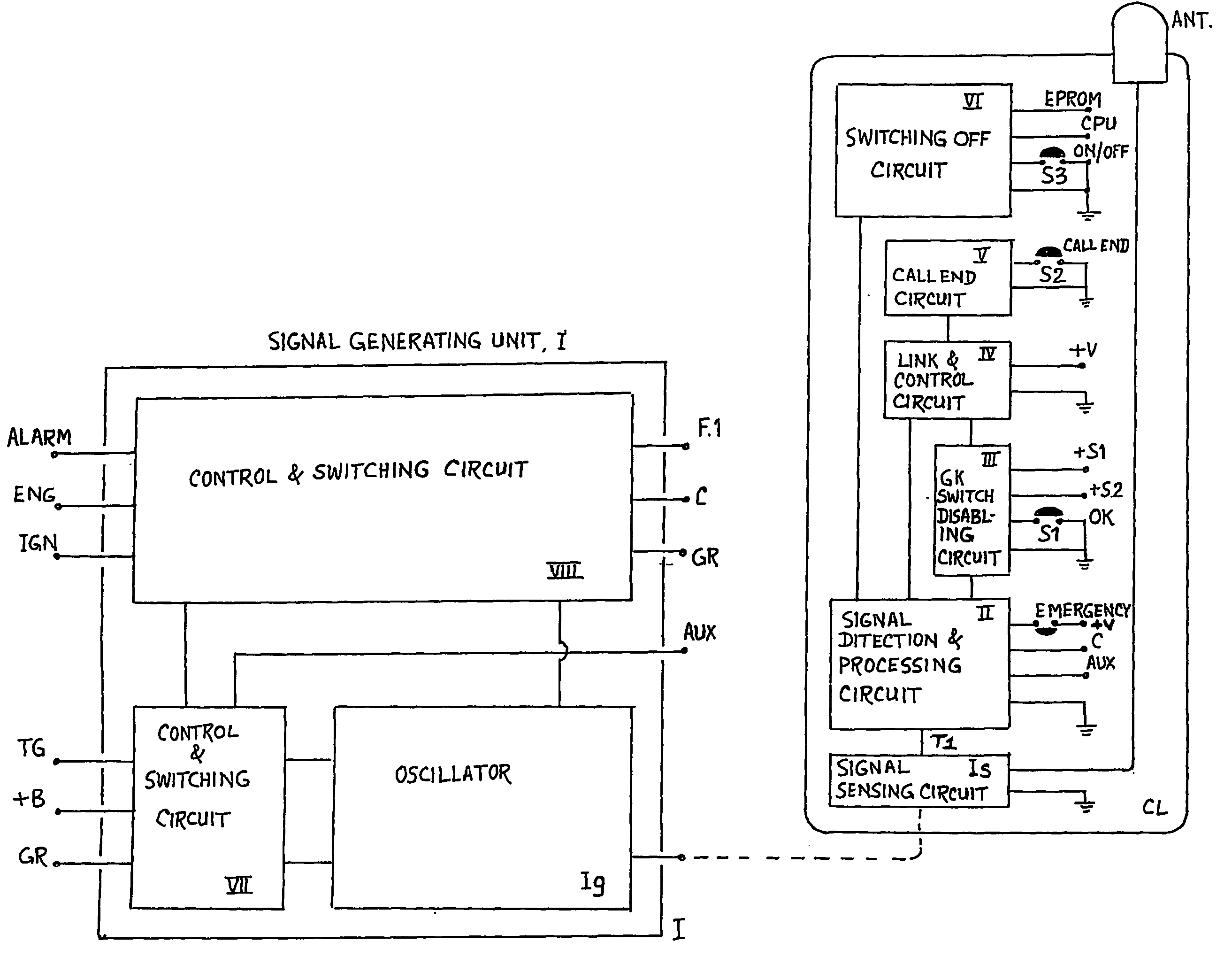
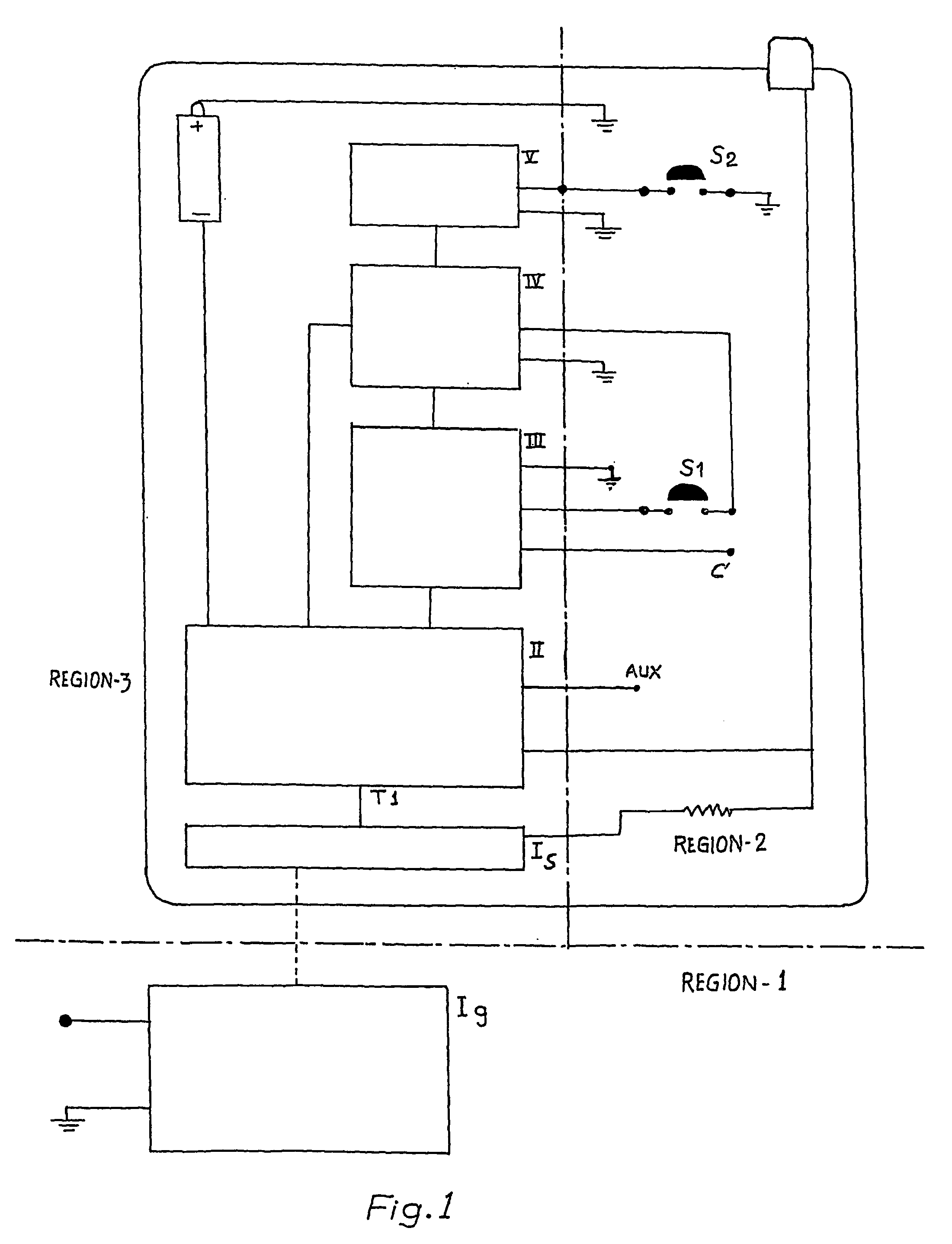
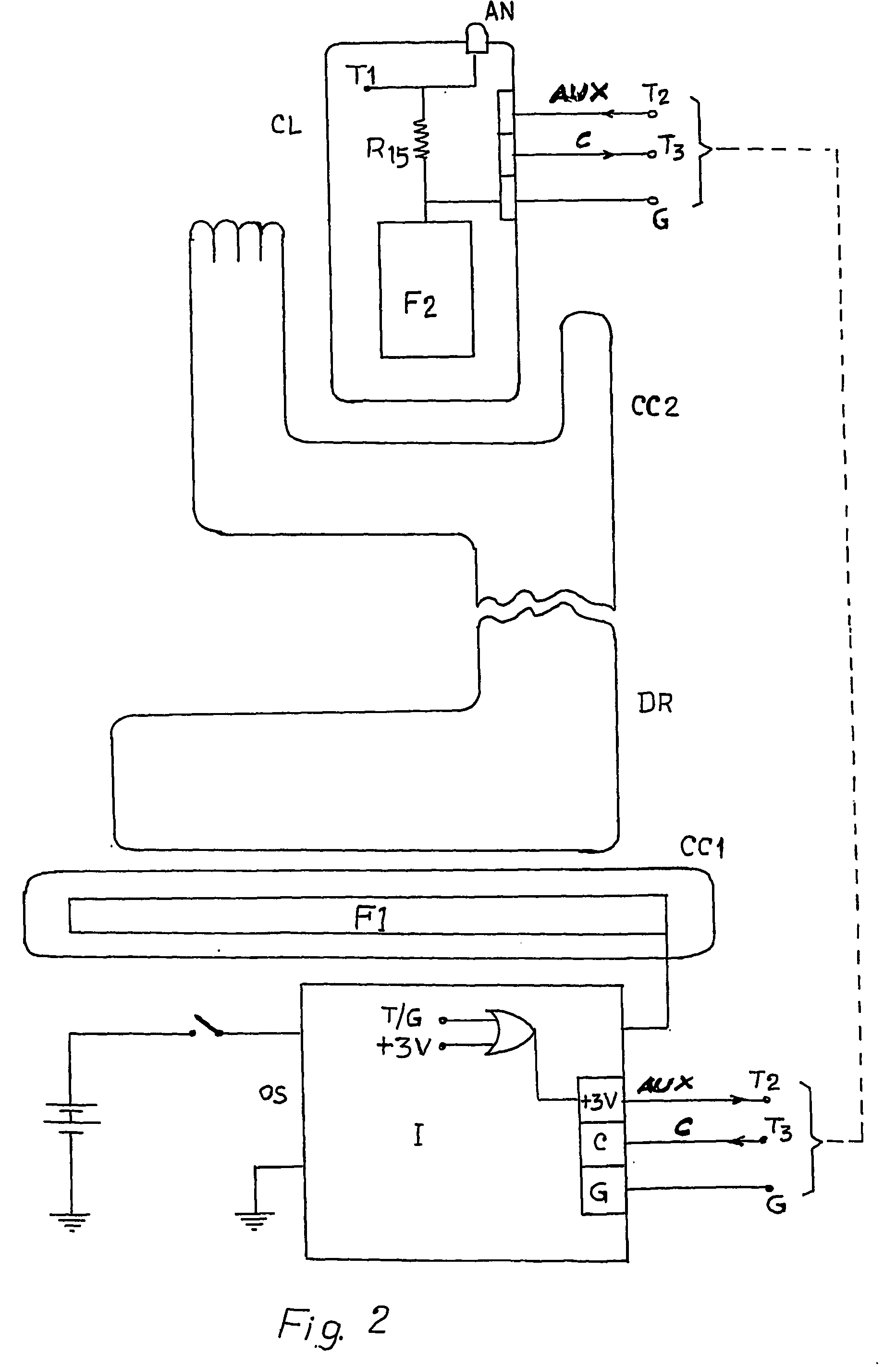
[0047]Referring to FIG. 1, the block diagram depicts a Signal Generating Unit I comprising a Signal Generating and Transmitter Circuit Ig that may be positioned either below the driver's seat or inside the dashboard of the vehicle. The Signal Generating Circuit Ig is linked to a conducting foil F1, enclosed inside the seat of the driver, and forming one part of a first capacitive coupling CC1 in a manner shown in FIG. 2. Another conducting foil F2 provided in the cellphone constitutes a part of the second capacitive coupling CC2, and links circuit Ig to a signal detection and processing circuit II through the terminal T1. The Signal Generating Circuit Ig is adapted to be connected to the power source through the Control Circuits of FIG. 4 or 6a, and would remain in the switched on condition as long as the ignition of the vehicle remains on and / or it is moving above a certain speed, and thus would signal the presence of the first condition.

[0048]The Signal Generator Circuit Ig is con...


PUM


Abstract

This invention relates to a system for disabling a cellphone in the presence of certain conditions, and for switching it off in the presence of some other conditions, while allowing its use in the normal fashion in the absence of these two sets of conditions. Thus, this system regulates cellphone use in accordance with specified restrictions in specific locations, and allows its normal functioning when these restrictions are not required. Specifically, a first condition is an attempt to operate a cellphone by the driver of a vehicle having its ignition on and / or moving above a certain speed. In such a condition the system would automatically disable the OK switch of a cellphone and may also perform the CALL END function. In the second condition the system automatically switches off any cellphone in the ON condition being carried on the person of an individual occupying a seat in an aircraft, or a committee room, or any other such location where such a restriction is envisaged. The system also makes a provision for automatic sequential dialing of a specified set of numbers like the police, medical services etc. during an emergency by allowing overriding any regulatory restriction. In addition, this invention also relates to control circuits provided in said system for preventing tampering with or bypassing the system by cellphone users.

Description

BACKGROUND OF THE INVENTION[0001]1. Field of the Invention[0002]This invention relates to a device which automatically disables or switches off a cellphone when first or second conditions are respectively present and automatically enables the cellphone when said conditions no longer exist. The first condition is an attempt to operate a cellphone by the driver of a vehicle when its ignition is on or it is moving above a certain speed. The second condition is when a person occupying a seat in various locations such as in an aircraft or auditorium endeavors to use the cellphone.[0003]2. Description of Related Art[0004]Reference is made to the first condition, namely an attempt to use a cellphone by the driver of a vehicle having its ignition on and / or moving above a certain speed. When a call is received, the user picks up the cellphone, looks at the number of the caller on its display panel, and switches on the OK switch of the cellphone in order to receive the call. In a likewise man...

Claims


Application Information

Patent Timeline
IPC IPC(8): H04Q7/20H04B1/38H04B7/00H04M1/00H04M1/60H04M1/66H04M1/72454H04M1/72463H04W4/30
CPCH04M1/66H04W4/04H04M1/72577H04M1/6041H04W4/027H04M1/72569H04M1/72454H04M1/72463H04W4/30
Inventor SINGH, YASH PALSINGH, ANIRUDHSINGH, MANUVERMA, LAKINDER SINGH
Owner SINGH YASH PAL
Learn More