
Method and device for operating a multiple component technical system, particularly a combustion system for producing electrical energy

a technology of electrical energy and technical system, which is applied in the direction of combustion control, adaptive control, instruments, etc., can solve the problems of automatic switching on and off, unable to realize the tasks of controllers usually used for accomplishing such tasks with very great effort, and can only be reproduced as technical control-related programs with considerable effort, so as to achieve the most economical operation

Inactive Publication Date: 2007-02-20
SIEMENS AG
View PDF13 Cites 24 Cited by
  • Summary
  • Abstract
  • Description
  • Claims
  • Application Information

AI Technical Summary

Benefits of technology

[0014]An object of the present invention is to provide a method and a device for operating an installation that includes a number of components, in particular a combustion installation for generating electrical energy, which permit the most economical possible operation of the technical installation.
[0024]In the case where the components are of the same type as one another, this has the effect that the assessment of at least one other component with a numerical value when there are changes in the operating state is particularly simple, since the values of the numerical values with which the components concerned are assessed do not have to be dependent on the function of a component per se, but only on the role of the component concerned which the latter plays in a certain operating state of the technical installation with regard to desired economical operation of the installation. This development means that, when establishing the values of the numerical values with which the assessment of other components takes place, less effort has to be expended, since peculiarities by which the components could be distinguished from one another do not have to be taken into account.
[0027]If the technical installation is a combustion installation with a number of bumers, which are arranged for example along the inside wall of a combustion chamber, a spatial distribution of burners that are in operation is may be advantageous, since as a result a homogeneous temperature profile is achieved in the combustion chamber and as a result the fuel supplied is used particularly efficiently and the installation is operated in an economical and material-conserving manner.
[0029]In this way a uniform spatial distribution of components that are in operation can be achieved particularly easily, since it is already taken into account in the assessment of the components that components spaced equally from a reference point, that is the arrangement location of a component to be switched on or off, are assessed the same. Accordingly, the desired equal spatial distribution is already included in the assessment and not only taken into account during or after the further processing of the numerical values (summation).
[0030]As already stated, the assessment is, for example, particularly advantageous whenever force is exerted by the components of an installation on a raw material, a product or a device, since a uniform exposure to force in this case minimizes risks to the raw material, the product or the device. Similarly, an assessment of this type is advantageous in the case of the already mentioned combustion installation with a number of burners arranged in a combustion chamber, since a uniform distribution of burners that are in operation is also desired here with regard to a uniform temperature profile in the combustion chamber, and can easily be achieved in this way.
[0033]It is also advantageous that a uniform, in particular symmetrical, spatial distribution of components that are in operation is achieved by the switching on or off of components.

Problems solved by technology

This may for example include incidents which could not be taken into account in every detail when the control system was designed, but also operational transitions during operation of the technical installation that in themselves are simple, from a human viewpoint, but which often can only be reproduced as technical control-related programs with considerable effort.
The recording of all possible operating states of a technical installation in a control program is often not possible in advance, so that in some cases the operating personnel of the technical installation have to take over operating the components of the technical installation manually.
In the case of a technical installation in which a number of components act together to perform a certain function, the previously described problems are similar.
Practical operation of many power plants shows that, for example in the case of the solution to the aforementioned problem of uniform distribution of burning in a combustion chamber, automatic switching on and off of the main burners is often relinquished, since the logic or step controllers usually used for accomplishing such tasks can only be realized with very great effort.
Additionally, the control programs that can be used for such purposes may be very complicated.
By this deliberate restriction to defined operating cases, such controllers are less flexible and human intervention continues to be necessary for all those operating cases for which no control commands are provided in the controllers.
A disadvantage of this is that additional devices, such as the measuring devices for determining the temperature profile, are necessary.
The additional effort is in this case is often considerable.
Moreover, the adding of additional measuring devices imposes sources of problems on the technical installation, which in the event that they do not function can lead to the technical installation shutting down.

Method used


Image

  • Method and device for operating a multiple component technical system, particularly a combustion system for producing electrical energy
  • Method and device for operating a multiple component technical system, particularly a combustion system for producing electrical energy
  • Method and device for operating a multiple component technical system, particularly a combustion system for producing electrical energy

Examples


Embodiment Construction

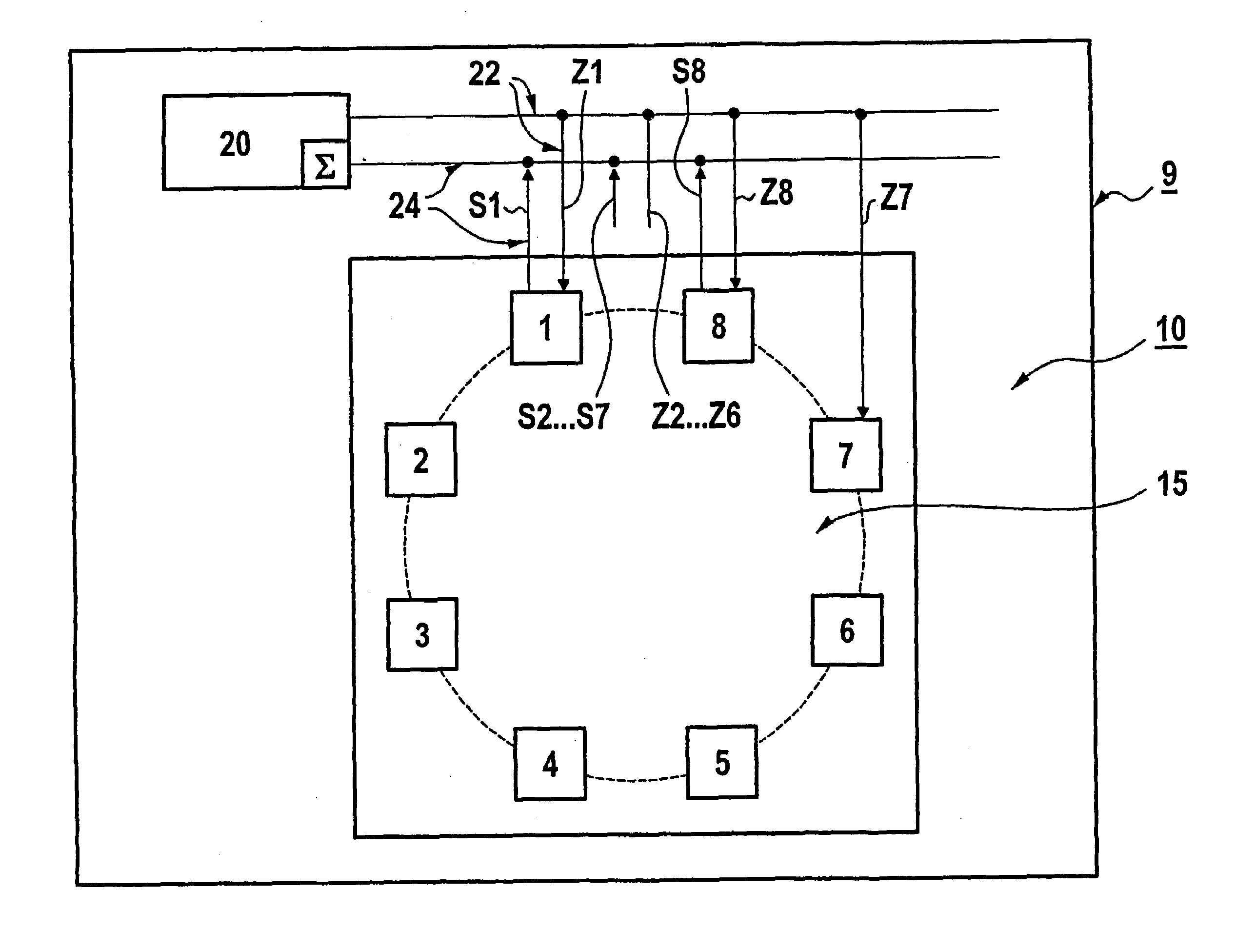
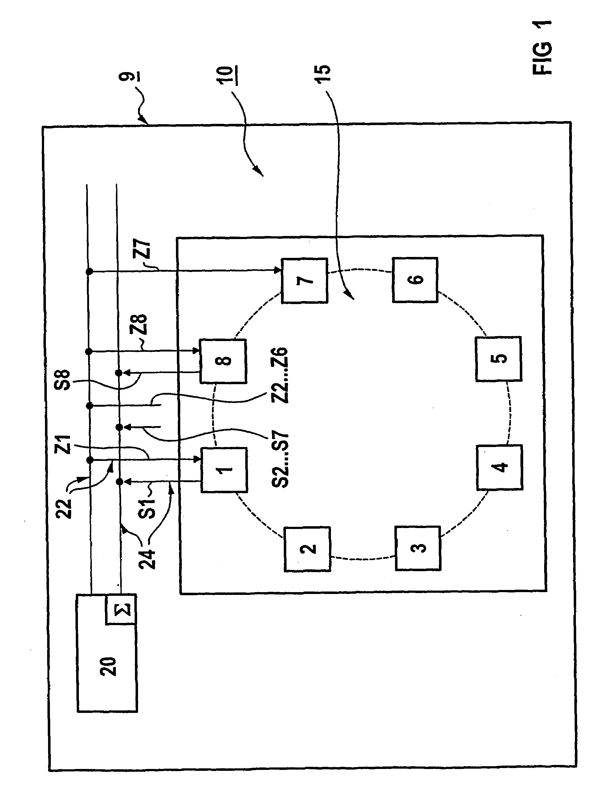
[0040]Represented in FIG. 1 is a device 9 for operating a technical installation 10, the latter comprising components 1, 2, 3, . . . 8, which are formed as burners and are arranged in a combustion chamber 15.

[0041]The device 9 includes an arithmetic unit 20, which is connected to the burners 1, 2, 3, . . . 8 via command lines 22 and sensor lines 24.

[0042]Via the sensor lines 24, the arithmetic unit 20 respectively receives from the burners 1, 2, 3, . . . 8 their operating state values S1, S2, S3, . . . S8. These operating state values contain, for example, information on whether the respective burner is switched on or off at the time.

[0043]In the arithmetic unit 20, the operating state values S1, S2, S3, . . . S8 are evaluated, in order in particular to establish a commencement or cessation of the operation of one or more burners. If this is the case, at least one other burner is assessed with a numerical value in the arithmetic unit 20.

[0044]Consequently, every change in operating ...


PUM


Abstract

In a technical system a plurality of values associated respectively with a component are stored in at least one computer unit. The computer unit is enabled to trigger an evaluation of at least one other component with a value when a component begins or terminates operation, and the values of each component are added. The computer unit is also enabled to determine which components should be started or stopped based on the added values.

Description

[0001]This application is the national phase under 35 U.S.C. § 371 of PCT International Application No. PCT / EP01 / 14601 which has an International filing date of Dec. 12, 2001, which designated the United States of America and which claims priority on European Patent Application number EP 00128305.0 filed Dec. 22, 2000, the entire contents of which are hereby incorporated herein by reference.FIELD OF THE INVENTION[0002]The present invention generally relates to a method for operating a technical installation which includes a number of components. The present invention also generally relates to a device for operating an installation that include a number of components. The technical installation may be a combustion installation for generating electrical energy.BACKGROUND OF THE INVENTION[0003]Technical installations generally include a number of components, which for example either each realize a specific function of the technical installation or together perform a certain function.[0...

Claims


Application Information

Patent Timeline
Patent Type & Authority Patents(United States)
IPC IPC(8): G05D23/00G05B13/02G06F19/00F23N1/00F23N5/24
CPCF23N1/002F23N2037/02F23N2023/08F23N5/24F23N2223/08F23N2237/02
Inventor SCHLICKER, STEFANSCHREIBER, ROLAND
Owner SIEMENS AG
Learn More