Method of installing a disk clamp over a hub of a disk drive

a technology of disk drive and clamp, which is applied in the field of computer disk drives to achieve the effects of reducing undesirable radial loading, and reducing disk coning and waviness

Inactive Publication Date: 2007-02-27
SEAGATE TECH HDD HLDG +3
View PDF14 Cites 11 Cited by
  • Summary
  • Abstract
  • Description
  • Claims
  • Application Information

AI Technical Summary

Benefits of technology

[0013]Other structural features of the disk clamp include an upper groove formed in the upper surface of the clamp for receiving a balance ring, and one or more lower concentric grooves. These lower concentric grooves help to distribute the load of the clamp on the underlying disk pack. Specifically, the ability to vary and control the load transmitted from the disk clamp to the disk pack minimizes deflection known as disk coning and waviness. Preferably, the contact surface of the lower flange is flat, which further reduces undesirable radial loading thus reducing disk coning and waviness. The larger contact area provided by the flat contact surface of the lower flange better compensates for locational misalignment between the clamp and a disk pack which naturally occurs due to tolerances in the manufacture of the clamp and of the disks. Particle generation resulting from movement of the contact surface relative to the disk is minimized thereby reducing disk drive contamination. The flat contact surface of the clamp remains in its contact position against a disk / spacer even during thermal cycles. Thus, there is no movement or displacement between the clamp contacting surface and the underlying disk / spacer. A rounded disk contact surface may displace (e.g., curl / uncurl) in response to thermal cycles which contributes to undesirable particle generation caused by a movement of the contact surface across the underlying disk / spacer.
[0014]The disk clamp of the present invention eliminates the need for using screws to secure the clamp to the hub. The clamp provides an axial force upon the disk pack which prevents the disk(s) from both axial and radial displacement with respect to the hub. O-rings or other stabilizing elements are not required to stabilize the connection between the disk pack and the hub because of the axial force which is provided by the disk clamp.
[0019]The disk clamp of the present invention, along with the methods of preloading and installation, and the various preloading devices each have a number of advantages. Use of a screwless disk clamp simplifies the overall disk clamp and hub arrangement, thus minimizing the cost of fabrication and assembly, reducing the likelihood of malfunction in the disk drive system, and providing effective and consistent disk drive performance. A preloading device which is able to preload the disk clamp further reduces potential disk drive contamination and damage. The preloading device further simplifies the construction of the disk drive because there is no need to provide additional support to the hub during clamp installation, and no separate means are required to prevent the disk pack from spinning during the installation.

Problems solved by technology

After a retaining ring is placed in a gap between a groove on the hub and the clamp, the load is removed which enables the disk clamp to spring back to its undeflected state; however, the retaining ring prevents full return resulting in the retaining ring being wedged between the clamp and the hub.
A rounded disk contact surface may displace (e.g., curl / uncurl) in response to thermal cycles which contributes to undesirable particle generation caused by a movement of the contact surface across the underlying disk / spacer.

Method used


Image

  • Method of installing a disk clamp over a hub of a disk drive
  • Method of installing a disk clamp over a hub of a disk drive
  • Method of installing a disk clamp over a hub of a disk drive

Examples


first embodiment

[0057]Referring also now to FIGS. 12 and 13, a retainer ring applicator group 142 is disposed within the adapter frame 140. A clamp press member 144 attaches to the distal end of the frame 140. The press assembly 138 is lowered in alignment with the disk clamp, and a predetermined amount of force is applied to deflect the clamp. The press assembly 138 may be lowered by means of an overhead gantry, (not shown), or some other positioning device which is also able to apply the predetermined amount of force for deflecting the clamp. Various control members may be incorporated within the press assembly to ensure that the desired amount of force is applied to deflect the clamp. For example, known stress and strain measuring devices such as strain gauges and the like may be attached to the disk clamp in order to measure deflection, and thus the amount of force applied. Clamp press member 144 serves the same function as the clamp press member 90 in the

[0058]Now referring to FIGS. 14 and 15,...

third embodiment

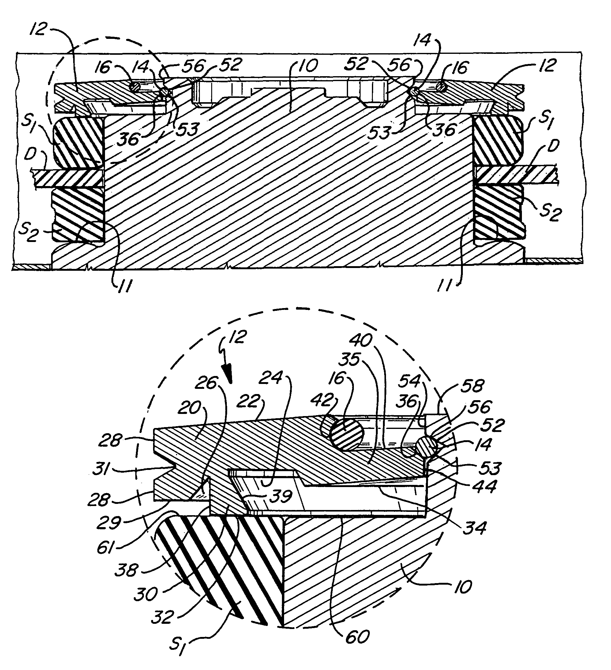
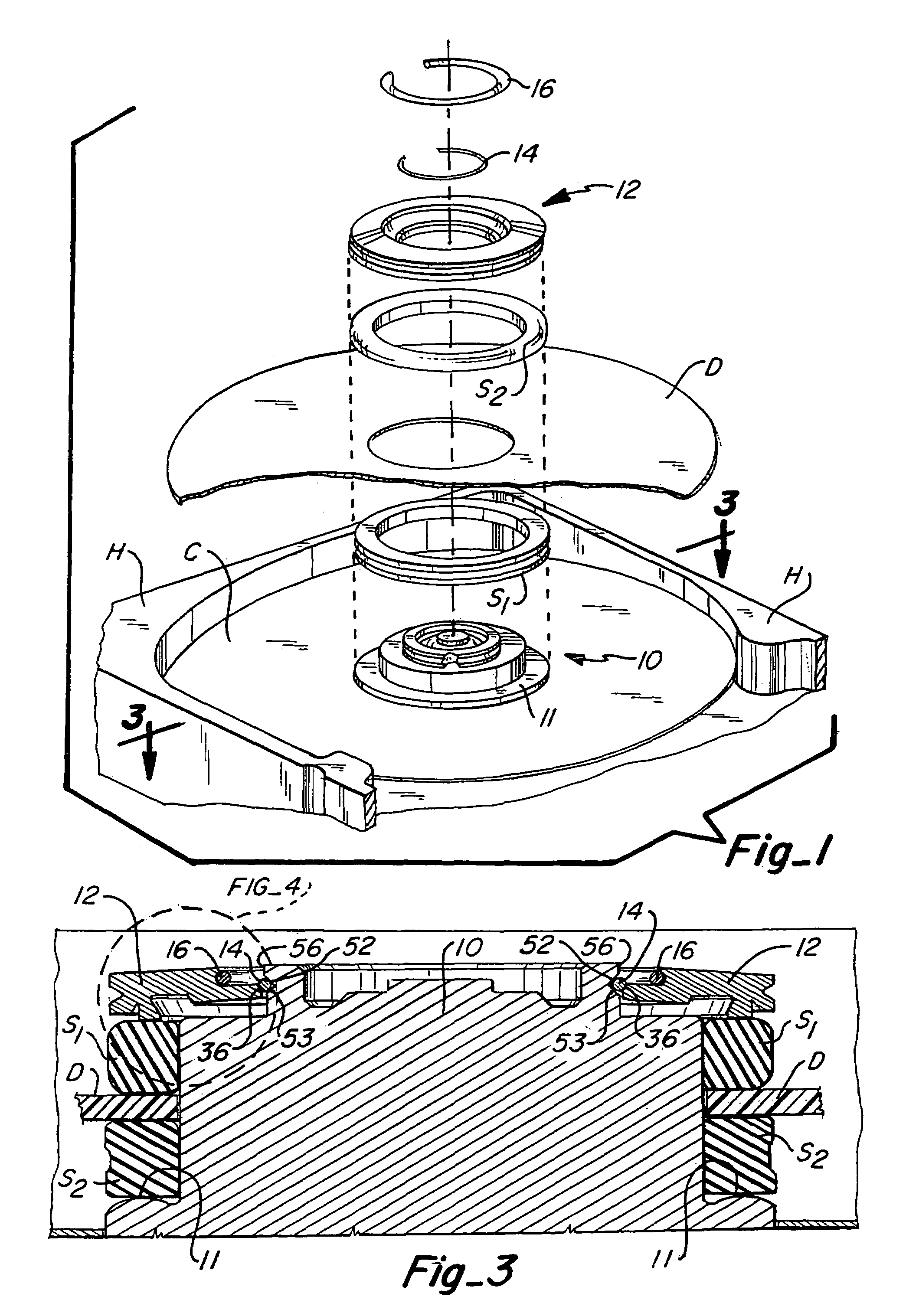
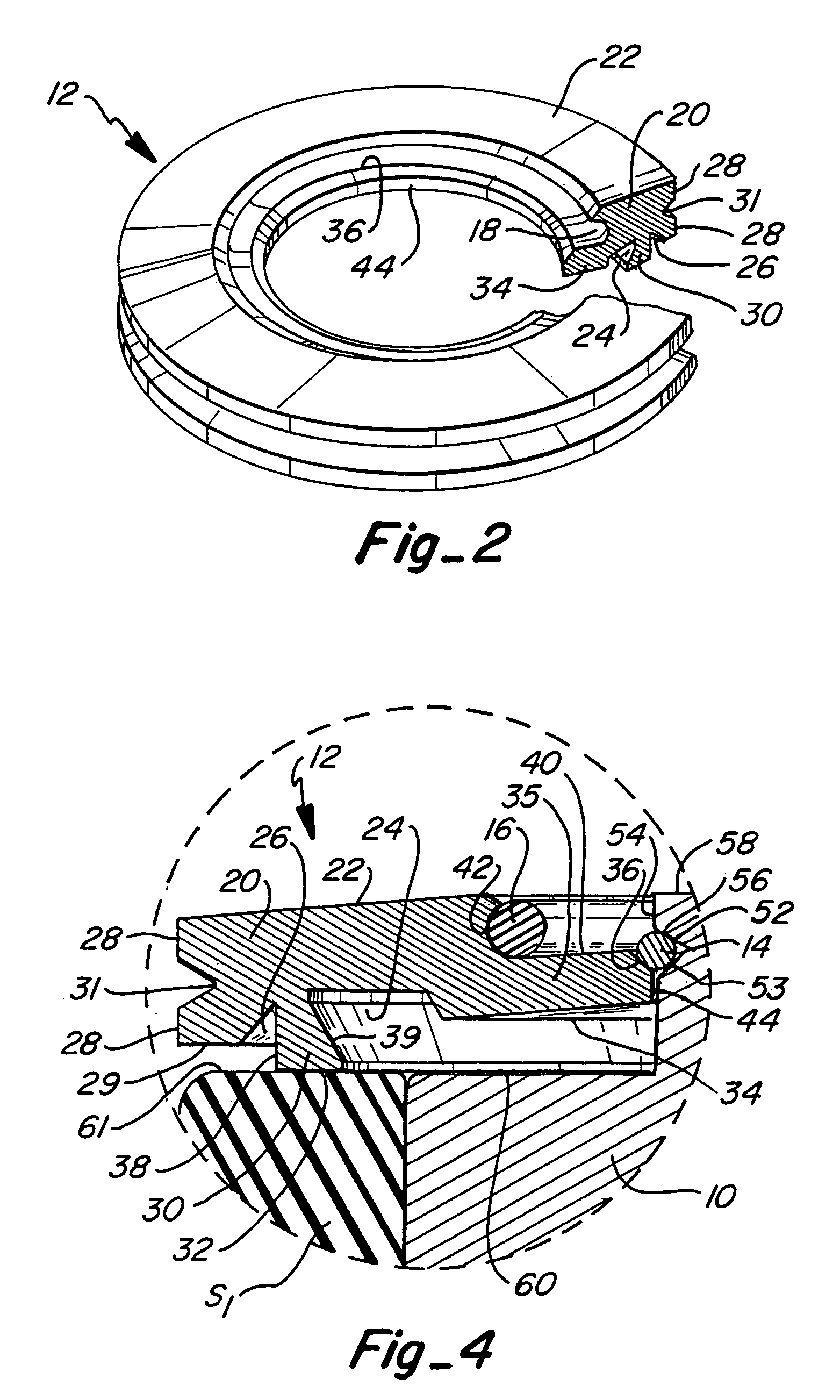
[0061]The retainer ring applicator 220 of the third embodiment is also similar to the retainer ring applicator of the previous embodiments. Specifically, the retainer ring applicator 220 includes an outer sleeve 222 which is a slidable over an inner core 224. A spring 226 is positioned within the inner core to bias the outer sleeve 222. A retainer ring 14 is placed over the distal end of the inner core 224. The retainer ring applicator 220 is then inserted within the opening 196, and the contacting flange 230 of the inner core 224 contacts the upper surface of the hub to align the retainer ring application with the hub. The outer sleeve 222 is pressed downward to dislodge the retainer ring from the distal end of the inner core 224, and to push the retainer ring in the gap between the clamp and the hub.

[0062]In each of the embodiments, after the disk clamp has been installed, the balance ring 16 may be inserted within the upper groove 18 of the disk clamp. As understood by those skil...


PUM

PropertyMeasurementUnit
distanceaaaaaaaaaa
forceaaaaaaaaaa
frictionaaaaaaaaaa

Abstract

A disk clamp is provided for securing one or more data storage disks to a disk drive without the need for screws. A preloading device is also provided for installing the disk clamp and removing the disk clamp after installation. The preloading device applies a load to the clamp to deflect the clamp, and allows a retaining ring to be positioned between the disk clamp and the hub of the disk drive. Preloading the disk clamp helps to reduce disk drive contamination, potential damage to the motor hub, and improves reworkability of the disk drive. The preloading device can be incorporated within a manually manipulated preloading device, or within an automated assembly process in which the preloading device is incorporated. Methods are also provided for clamp preloading and clamp installation.

Description

CROSS REFERENCE TO RELATED APPLICATION[0001]The present application is a divisional of U.S. patent application Ser. No. 10 / 123,275, filed Apr. 15, 2002, now U.S. Pat. No. 6,816,338 entitled DISK CLAMP FOR DISK DRIVE, AND APPARATUS AND METHOD FOR PRELOADING DISK CLAMP”, which is incorporated herein by this reference.[0002]Priority is claimed from U.S. Provisional Patent Application No. 60 / 304,262, filed on Jul. 9, 2001, entitled “Screwless and Preloadable Disk-Clamp for Rigid Disk Files”, the disclosure of which is incorporated herein by reference in its entirety.FIELD OF THE INVENTION[0003]The present invention relates to computer disk drives, and more particularly, to a disk clamp for a disk drive, and an apparatus and method for preloading the disk clamp in order for installation within the disk drive.BACKGROUND OF THE INVENTION[0004]Disk drive data storage systems typically include one or more data storage disks mounted to a spindle hub, and a spindle motor drives the spindle hub...

Claims


Application Information

Patent Timeline
Patent Type & Authority Patents(United States)
IPC IPC(8): G11B5/127H04R31/00G11B17/028G11B17/038
CPCG11B17/0287G11B17/038Y10T29/49027Y10T29/49025Y10T29/5313
Inventor SUWITO, WANTJINARJOFAHEY, JAMES D.
Owner SEAGATE TECH HDD HLDG
Why Eureka
Try Eureka