Methods and devices for enhancing intensity of on-surface lines cast by laser line projectors or the like

a laser line projector and laser line technology, applied in the field of methods and, can solve the problems of limiting the useful length of the output line of the projector, difficulty in forming a projected line of uniform beam intensity along a long wall, and the use of such manual aimed, small and portable projectors

Inactive Publication Date: 2007-02-27
ZIRCON
View PDF25 Cites 15 Cited by
  • Summary
  • Abstract
  • Description
  • Claims
  • Application Information

AI Technical Summary

Problems solved by technology

A problem persists in the use of such manually aimed, small and portable projectors.
It is difficult to form a projected line of uniform beam intensity (reflected intensity) along a long wall, say one that is about 10 to 30 feet or longer.
Government regulations limit the maximum power output of manually aimed projectors to about 5 milliwatts (5 mW, this maximum also known as Class IIIA) and this limitation in turn limits the useful length of the projector's output line.
The reason for the power limitation is that users can accidentally point the output laser beam directly toward an eye and injure themselves or others.
Users typically note that the intensity of the illuminated line on the wall paradoxically appears to be strongest near its far end (about 6–10 feet away from the projector housing) and that unexplainably weakens as one gets closer to the projector.
A problem which arises with such fanout-generated lines is that sometimes workmen wish to work on a wall region that is beyond the planned end point of a given line projector.
Such remounting can be cumbersome and time consuming.

Method used


Image

  • Methods and devices for enhancing intensity of on-surface lines cast by laser line projectors or the like
  • Methods and devices for enhancing intensity of on-surface lines cast by laser line projectors or the like
  • Methods and devices for enhancing intensity of on-surface lines cast by laser line projectors or the like

Examples


embodiment 760

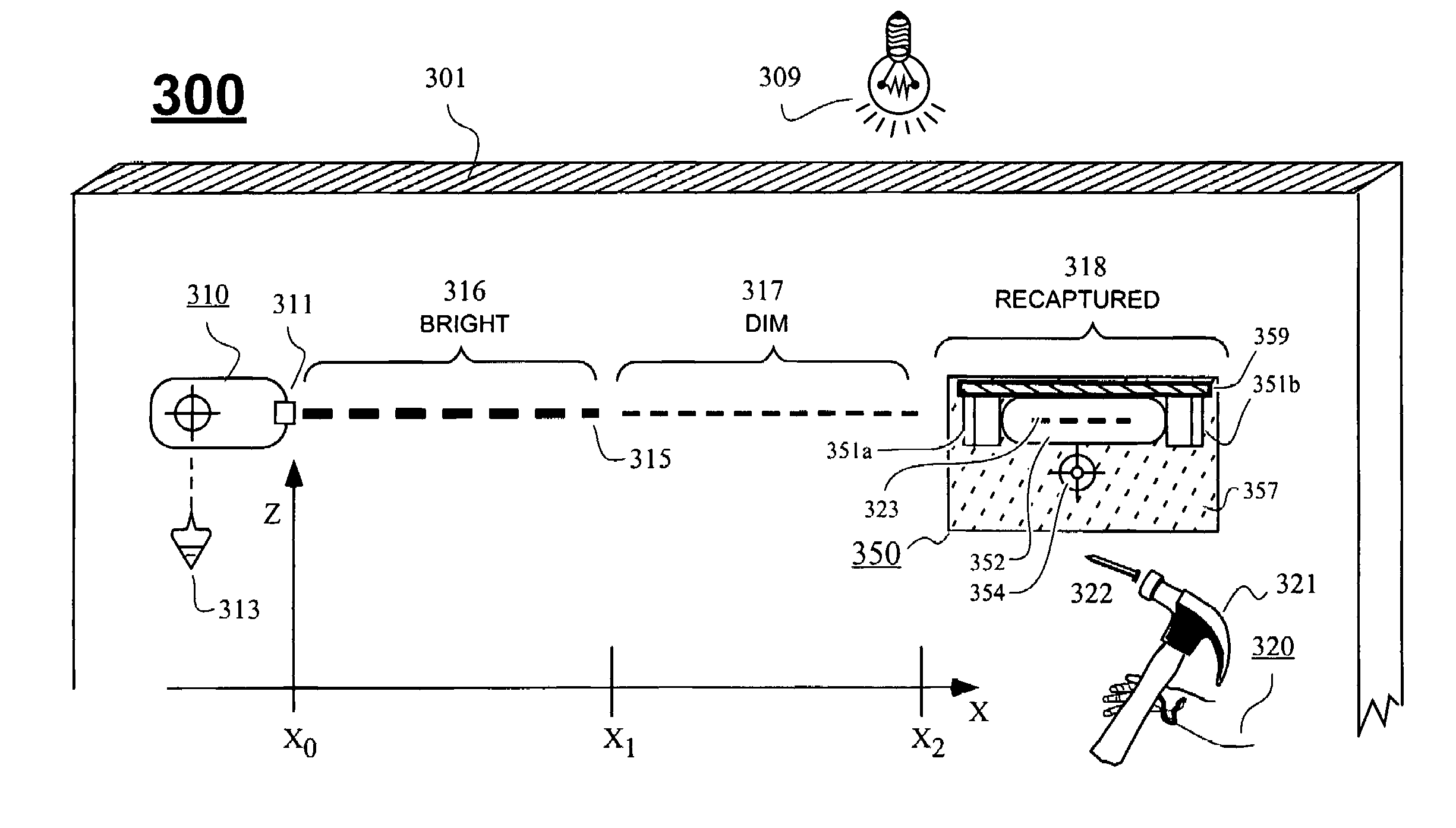
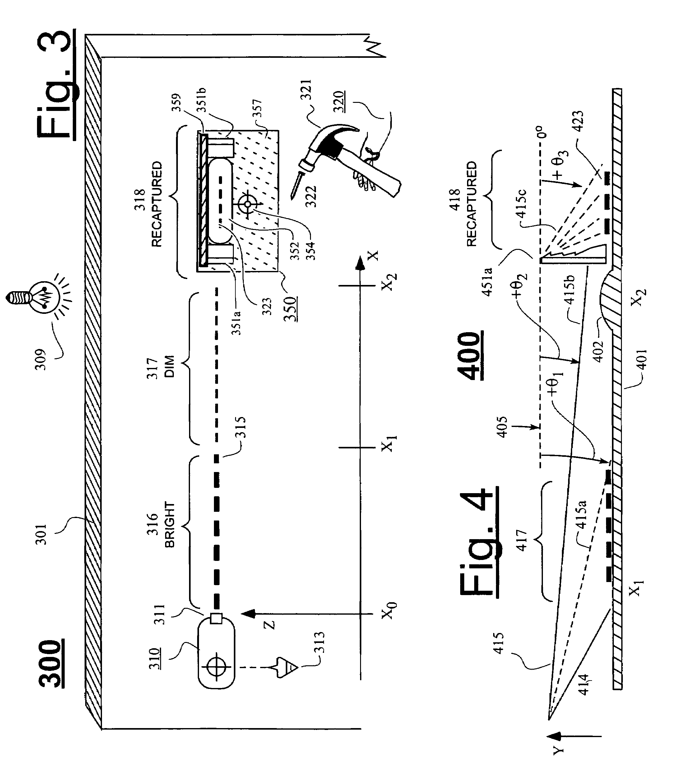
[0043]Working Example: A working example of embodiment 760 was constructed by taking stock, transparent square plastic rods (believed to be acrylic) having a side width of about 0.5 inch, milling one corner off at about 35°, polishing the milled surface and cutting off two pieces to thereby create the 7-surface structures as substantially shown at 751a and 751b. The 7-surface structures were glued in counterfacing relation, as substantially shown at 751a and 751b and also at 351a–351b in FIG. 3, to a clear plastic support plate such as 357 of FIG. 3. An aperture was defined through the support plate such as shown at 352 and a shadowing shroud made of a flexible dark plastic was glued to the 7-surface structures as is substantially shown at 359. The plastic support plate (357) was adhered to a wall scanner 761 (sometimes referred to as a studfinder) which emits a marking light 763 when a wall-hidden structure such a wooden stud is detected (e.g., via sensing of change in capacitive l...

embodiment 770

[0044]For the other embodiment 770 shown in FIG. 7, the projection enhancer 752 may be constituted by a plate-like fresnel structure of refractive and / or reflective elements that pivotally attach to a marked ruler or square 771. The plate-like fresnel structure may removably clip onto the ruler body and / or may slideably move along it so that the enhanced line extension (623) appears on the ruler 771 itself or on a work-surface adjacent to the ruler. Once again, the projection enhancer 752 is operatively coupled to the ruler means 771 so that a user (720) can simultaneously move both the ruler 771 and the enhancer 752 with just one hand 720 while searching against wall region 718 for one or a combination of both of a distance from a known reference (e.g., an exposed nail head) and a linear extension or enhancement of laser line 715. The user can use the free other hand (not shown) to mark the spot or drill a hole or otherwise operate on the located position. Thus the user 720 can con...


PUM


Abstract

Given a situation where a projected laser line appears to have terminated or faded as it intersects with a work-surface (e.g., a wall), a fan-out redirecting means is used to capture and redirect energy radiating above and parallel to, or radiating away from the given work-surface area, where the captured energy is from a line projector mounted to the surface. The radiation capturing and redirecting means aims the captured energy at a greater angle towards the work-surface so that the redirected light is thereafter reflected back to a user to give the perception that a line of enhanced intensity or reborn existence is being created on the work-surface or on a reflective overlayer placed against the work-surface. The radiation capturing and redirecting means may include one or both of optically refractive means and optically reflective means (e.g., lens and mirrors) for performing the capturing and / or redirecting functions.

Description

FIELD OF DISCLOSURE[0001]The invention relates generally to laser line, or other lighted line projectors such as used in the construction industry for projecting straight lines along walls or other objects. The disclosure relates more specifically to enhancements which increase the effective length and / or intensity of the projected lines along a surface.DESCRIPTION OF RELATED ART[0002]Laser line projectors have been a boon to the construction industry, helping workmen to layout straight and leveled or plumbed lines along walls or other objects. Many designs for laser line projectors exist, ranging from very complicated and expensive ones that mount on large tripods, generate a plurality of very precise beams of light in different directions and automatically level and precisely square up their respective beams; to very simple and inexpensive ones where the user is expected to manually orient the projector while supporting the projector on a work-surface (typically a planar wall of a...

Claims


Application Information

Patent Timeline
Patent Type & Authority Patents(United States)
IPC IPC(8): G01C15/00G02B5/04G03B21/26
CPCG01C15/004Y10S33/21
Inventor KRANTZ, NORMAN L.MILLER, LARRY
Owner ZIRCON
Why Eureka
Try Eureka