Indexable insert

a technology of indexable inserts and inserts, which is applied in the direction of cutting inserts, manufacturing tools, shaping cutters, etc., can solve the problems of inability to reliably process, and inability to reliably control such chips, so as to reduce the breaking effect of chips, reduce the resistance of chips, and inhibit reliable processing.

Inactive Publication Date: 2007-02-27
MITSUBISHI MATERIALS CORP
View PDF29 Cites 53 Cited by
  • Summary
  • Abstract
  • Description
  • Claims
  • Application Information

AI Technical Summary

Benefits of technology

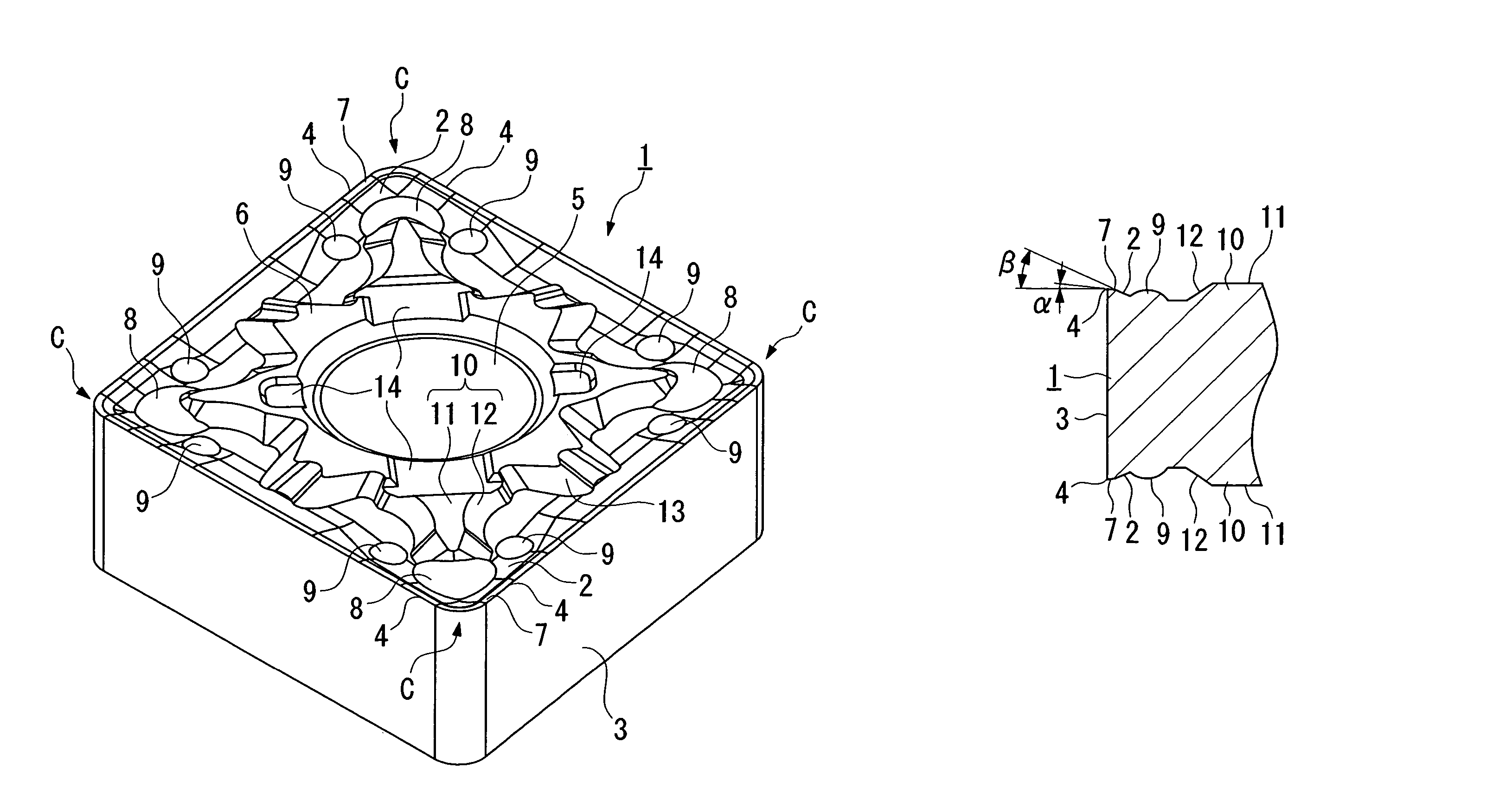
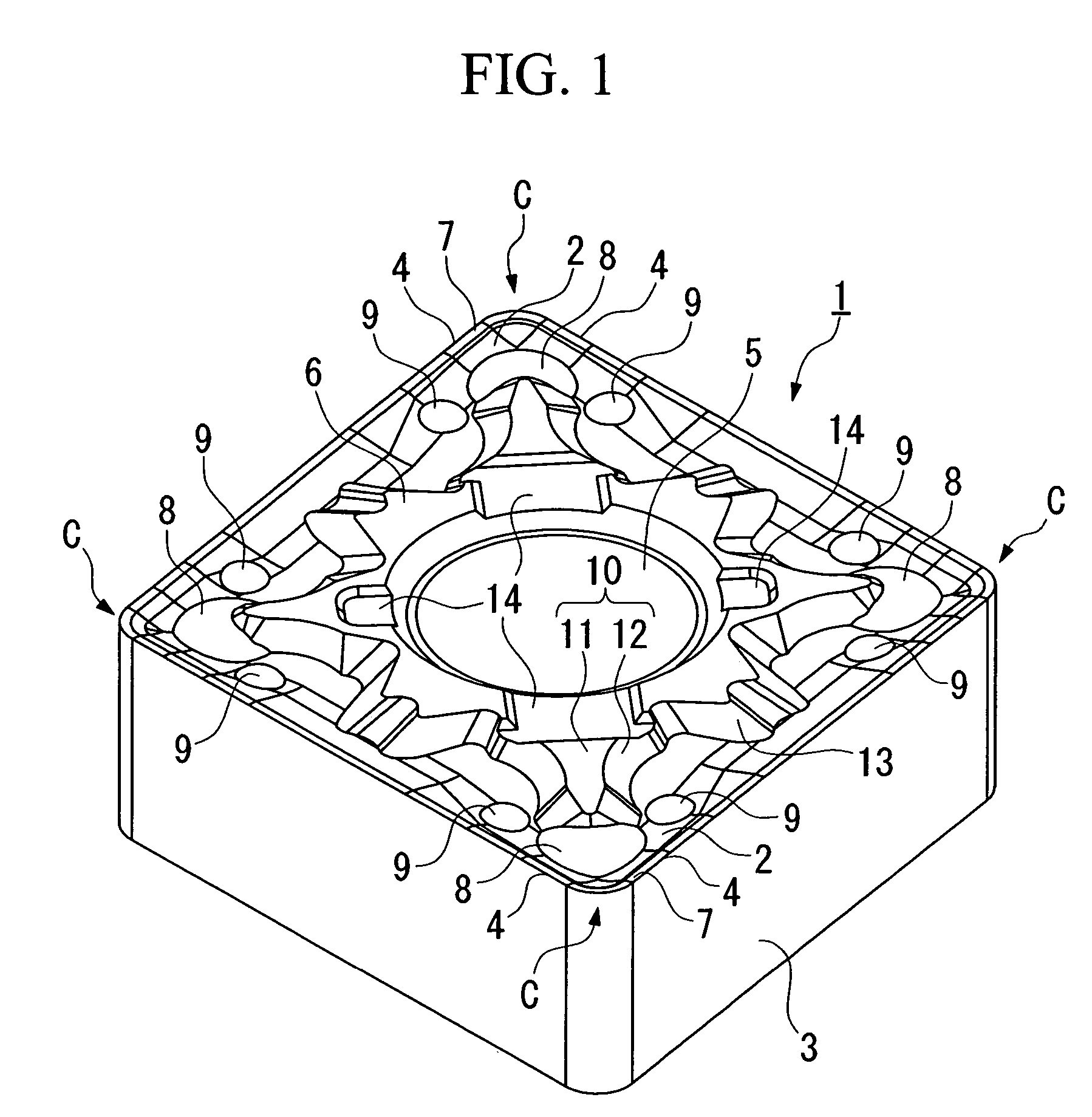
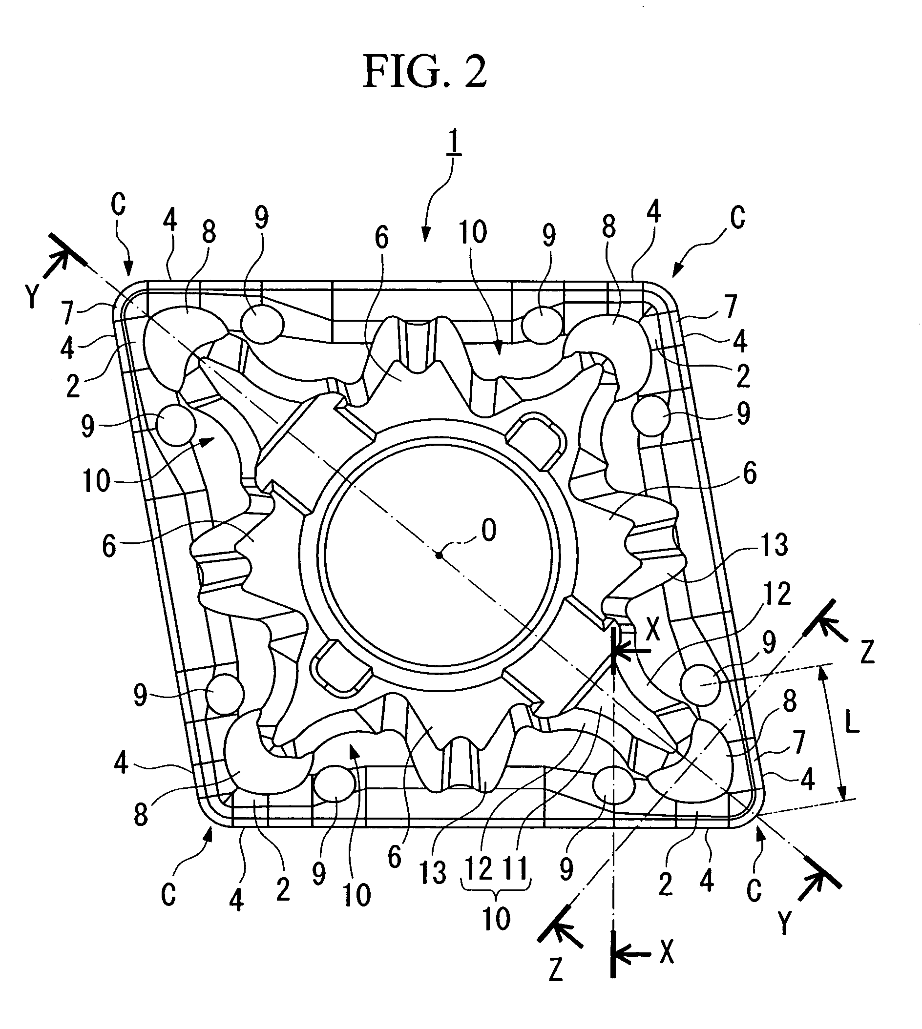
[0008]On the other hand, by gradually reducing the land angle and the rake face along the cutting edge, the wide chip produced when turning in the direction to raise the end face part of the work is curled by gradient bending force in the width direction, and flows out in a condition wherein it is readily broken in the longitudinal direction, that is, the direction of outflow. This chip then collides with the main convex provided on the tip of the corner part on the rake face, and the sub convex provided at the position away from this main convex, and receives the resistance in the direction of outflow to be curled, so that the chip is readily broken and processed. Moreover, since the primary and sub convexes are spherical face shape, they can collide with the chip at a point contact even if the outflow direction of the chip changes, so that stable chip control can be achieved between the external diameter part, the rounded part and end face part. It may be such that at least one pair of the sub convexes per one corner part, that is, at least one per one cutting edge, is provided, and if the cutting edge used is long, a plurality of sub convexes may be provided at intervals to the single cutting edge.
[0009]Here, in a case where one of the main convexes is formed on the tip side on the corner part of the rake face, by arranging such that the radius of the convex spherical face formed by the main convex is larger than the radius of the convex spherical face formed by the sub convex, and the top position of the main convex in the thickness direction of the aforementioned insert is higher than the highest point of the sub convex, then when narrow chip is produced on the corner part, the chip can be made to collide with the surface facing the corner part side of the main convex with the larger radius and higher highest point, in order to obtain reliable chip control. On the other hand, even when wide chip is produced using a cutting edge of a certain length, the chip can be made to collide with the surface facing the cutting edge side of this main convex, and the sub convex, in order to obtain reliable chip control.

Problems solved by technology

Therefore, even if a breaker for chip control is formed on the rake face of the insert T, in the case where the breaker is provided to produce narrow chip, when wide chip is produced in back feed cutting in corner cutting, or cutting of the rounded part, it cannot reliably be processed.
Conversely, when a breaker is provided to handle wide chip, narrow chip produced during cutting of the outer periphery part is not broken and extends in a long length, winding around the shank of the cutting tool, inhibiting better chip control.
Moreover, when the direction of outflow of the chip changes while cutting the rounded part between the external diameter part and the end face part, it is also difficult to reliably control such chip.
However in such inserts, since the chip is simply flowed out along the breaker groove onto the inside of the rake face and collides with the aforementioned respective projections to be broken, the effect of fragmenting the chip and changing the direction of outflow are small.
Furthermore if the width of the breaker groove between the aforementioned elliptical projection and the cutting edge is reduced to suit back feed cutting in corner cutting, the problem occurs such that chip jamming occurs while cutting the external diameter part by cutting at a large depth of cut or at high feed, or such that it is unable to control the direction of outflow of the chip by processing the rounded part.

Method used


Image

  • Indexable insert
  • Indexable insert
  • Indexable insert

Examples


examples

[0073]Here, FIG. 23 shows the shape of chip due to the insert of the first embodiment shown in the FIG. 1 to FIG. 6, and FIG. 24 and FIG. 25 shows, in comparison to this, the shape of chip due to the insert of the first and the second comparative examples, for the case where the feed rate was 0.1 to 0.2 mm / rev, and the depth of cut was 1 mm. At first, the condition of the chip is shown for the case where as, shown in FIG. 26, an end face part P is formed orthogonal to the rotation axis of the work W, an external diameter part Q is formed orthogonal extending parallel to the rotation axis S, and a chamfered part M formed is formed orthogonal on the part where the end face part P and the external diameter part Q intersect. In the respective figures, the parts shown by the reference symbols P, Q, and M, are chip produced by the cutting of the end face part P, the external diameter part Q, and the chamfered part M. However, in FIG. 23, the chip of the end face part P and the chamfered p...


PUM

PropertyMeasurementUnit
thicknessaaaaaaaaaa
thicknessaaaaaaaaaa
angles of inclinationaaaaaaaaaa

Abstract

An object of the invention is to reliably control chip, particularly that produced in profiling. To achieve this, rake faces are formed on polygon faces of an insert in the form of a polygonal plate shape, and a pair of cutting edges extending respectively from corner parts of the polygon faces are formed on a ridge part of the polygon faces, and each of the rake faces is gradually inclined as it becomes farther away from the cutting edge, and a land formed along the cutting edge, is inclined so that it gradually sinks as it become farther away from the cutting edge at an angle of inclination smaller than a rake angle, and angles of inclination of these rake face and land are made smaller in the direction to separate from a tip of the corner part along the cutting edge, and a main convex being a convex spherical face shape is formed at intervals between the cutting edges, on the corner part C, and at least one pair of sub convexes being a convex spherical face shape is also formed respectively at positions away from this main convex, along the pair of cutting edges.

Description

CROSS-REFERENCE TO PRIOR APPLICATION[0001]This is a U.S. national phase application under 35 U.S.C. §371 of International Patent Application No. PCT / JP02 / 12058 filed Nov. 19, 2002, and claims the benefit of Japanese Patent Application Nos. 2001-354459 filed Nov. 20, 2001; 2002-79717 filed Mar. 20, 2002 which are incorporated by reference herein. The International Application was published in Japanese on May 30, 2003 as WO 03 / 043767 A1 under PCT Article 21(2).TECHNICAL FIELD[0002]The present invention relates to an indexable insert (hereunder, insert) employed particularly in profile machining to improve the chip control.BACKGROUND ART[0003]In profile turning using a cutting tool, since the direction of feed, and depth of cut, of the cutting tool changes according to the shape of the work, the chip produced by the cutting edge of the insert mounted at the tip of the cutting tool also sequentially changes in its direction of outflow, width, and thickness. For example, as shown in FIG....

Claims


Application Information

Patent Timeline
Patent Type & Authority Patents(United States)
IPC IPC(8): B23P15/30B23B27/22B23B27/14B23B27/16
CPCB23B27/141B23B2200/0428B23B2200/049B23B2200/0495B23B2200/081B23B2200/082Y10T407/24B23B2200/161B23B2200/163B23B2200/321Y10T407/245Y10T407/23B23B2200/085B23B27/22
Inventor KITAGAWA, YOSHIHIROWATANABE, KENSUKEICHINOSEKI, OSAMUSUGAWARA, KENJI
Owner MITSUBISHI MATERIALS CORP
Why Eureka
Try Eureka