Optimum Utilization of slot gap in PIFA design

Inactive Publication Date: 2007-02-27
CENTURION WIRELESS TECH INC
View PDF16 Cites 32 Cited by
  • Summary
  • Abstract
  • Description
  • Claims
  • Application Information

AI Technical Summary

Benefits of technology

[0022]In the construction and arrangement of the present invention such an exclusive resonant band is provided wherein the radiating element and the shorted parasitic element are in a common plane. In the present invention (see FIG. 8) a shorted parasitic element is placed with

Problems solved by technology

The introduction of a slot within a PIFA's radiating element has the undesirable effect of reducing the effective surface area of the radiating element, which in turn le

Method used


Image

  • Optimum Utilization of slot gap in PIFA design
  • Optimum Utilization of slot gap in PIFA design
  • Optimum Utilization of slot gap in PIFA design

Examples


Embodiment Construction

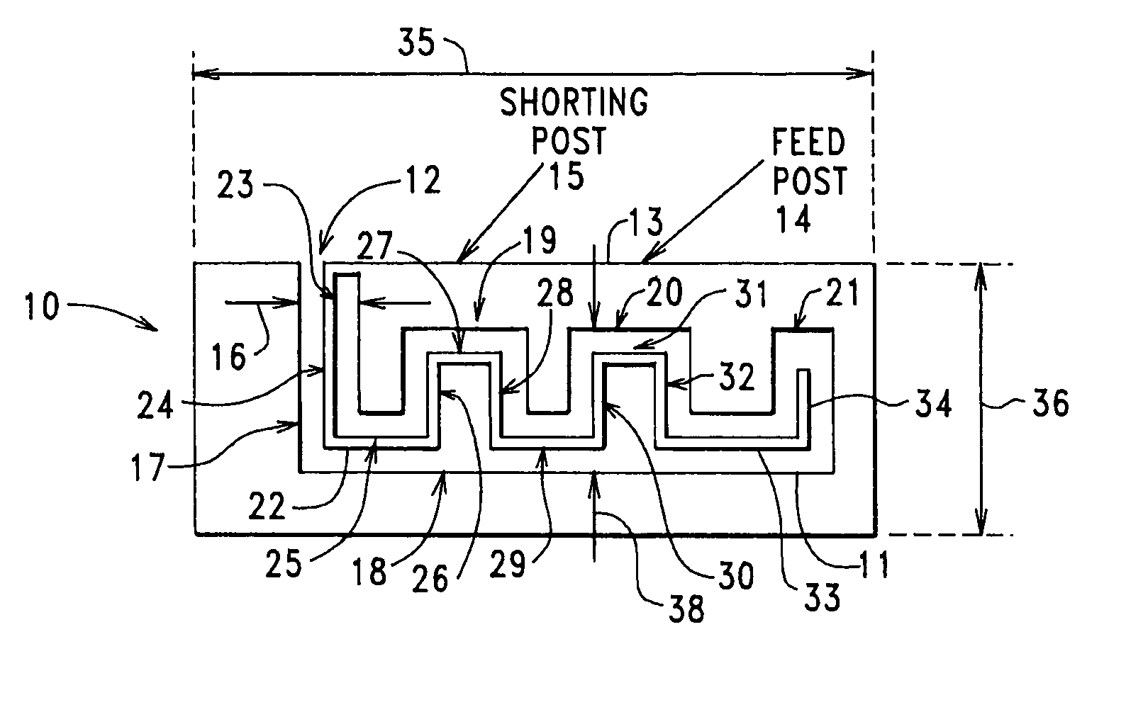
[0033]FIG. 1 illustrates a first embodiment of the invention.

[0034]As with other embodiments of this invention to be described, a top view of a radiating element is shown, it being understood that the radiating element is spatially associated with a ground plane, much as is shown in prior art FIG. 10. For purposes of simplification, the ground plane that is associated with embodiments of this invention is not shown in FIGS. 1–8.

[0035]FIG. 1 is the top view of a generally flat or planar metal radiating element 10 of a PIFA constructed and arranged in accordance with this invention, radiating element 10 including a meandering-path slot 11 that is generally L-shaped. The open end 12 of L-shaped slot 11 lies on the radiating element's non-radiating edge 13, i.e. the edge of radiating element 10 that contains a downward extending shorting post or shorting area 15 whose bottom end electrically connects to the PIFA's metal ground plane (not shown). In FIG. 1, a feed post or feed area 14 is...


PUM


Abstract

Operating parameters of a planar antenna are controlled by providing a planar metal radiating element having an edge, by providing a slot within the radiating element, the slot having side walls, an open slot-end that lies on the edge of the radiating element, and a closed slot-end the lies within the radiating element, and by providing a thin, line-like, and metal segment, at least a portion of which is coplanar with the radiating element and that extends from the open slot-end to the closed slot-end without physically engaging the slot's side walls. The metal segment can be connected to the antenna's ground plane to thereby form a parasitic element, or the metal segment can be connected to the radiating element to thereby form an extension of the radiating element.

Description

CROSS REFERENCE TO RELATED APPLICATIONS[0001]This non-provisional patent application claims the priority of U.S. Provisional Patent Application Ser. No. 60 / 424,850, filed Nov. 8, 2002, entitled “OPTIMUM UTILIZATION OF SLOT GAP IN PIFA DESIGN”, incorporated herein by reference. United States Non-Provisional patent application Ser. No. 10 / 135,312, filed Apr. 29, 2002, entitled “SINGLE FEED TRI-BAND PIFA WITH PARASITIC ELEMENT”, incorporated herein by reference, provides a parasitic element within an interior region that exists between the radiating element and the ground plane of a PIFA, this parasitic element being connected to the ground plane.FIELD OF THE INVENTION[0002]This application relates to receiving / transmitting radio wave antennas, for example antennas for use in wireless communication, and more specifically to planar antennas such as microstrip antennas and planar inverted-F antennas (PIFAs) that have a slot in the receiving / transmitting radiating element thereof (hereina...

Claims


Application Information

Patent Timeline
IPC IPC(8): H01Q1/24H01Q1/38H01Q5/00H01Q5/371H01Q5/378H01Q9/04
CPCH01Q1/243H01Q1/38H01Q5/378H01Q9/0442H01Q5/371H01Q9/0421H01Q13/10H01Q1/24
Inventor KADAMBI, GOVIND RANGASWAMYHARDY, WILLIS RAYMONDYARASI, SRIPATHIHEBRON, THEODORE SAMUEL
Owner CENTURION WIRELESS TECH INC
Why Eureka
Try Eureka