Co-simulation via boundary scan interface

a boundary scan and interface technology, applied in the direction of cad circuit design, program control, instruments, etc., can solve the problems of non-trivial creation from scratch, burden of obtaining suitable logic cores for implementing interfaces on devices, and substantial barriers for designers seeking to exploit the advantages of co-simulation

Active Publication Date: 2007-02-27
XILINX INC
View PDF14 Cites 9 Cited by
  • Summary
  • Abstract
  • Description
  • Claims
  • Application Information

AI Technical Summary

Benefits of technology

[0007]The various embodiments of the invention provide methods and apparatus for interfacing a high-level modeling system (HLMS) with a reconfigurable hardware platform for co-simulation. In one embodiment a boundary-scan interface is coupled to the HLMS and is configured to translate HLMS-issued commands to signals generally compliant with a boundary-scan protocol, and translate signals generally compliant with a boundary-scan

Problems solved by technology

For example, it is sometimes useful to take existing HDL components that have been designed using a tool separate from the HLMS and incorporate the HDL components into an HLMS simulation environment.
Even though these interfaces are common

Method used


Image

  • Co-simulation via boundary scan interface
  • Co-simulation via boundary scan interface
  • Co-simulation via boundary scan interface

Examples


Embodiment Construction

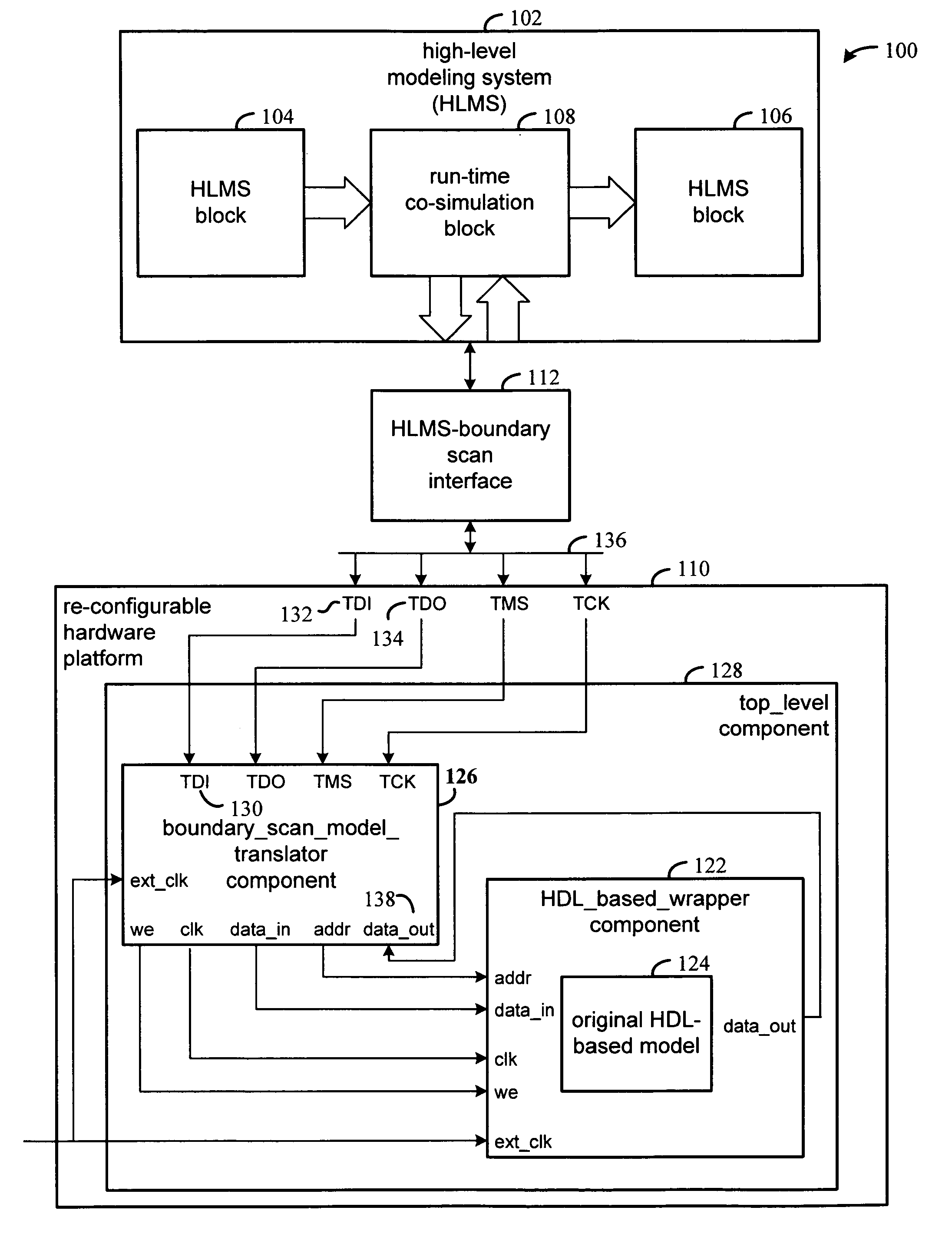
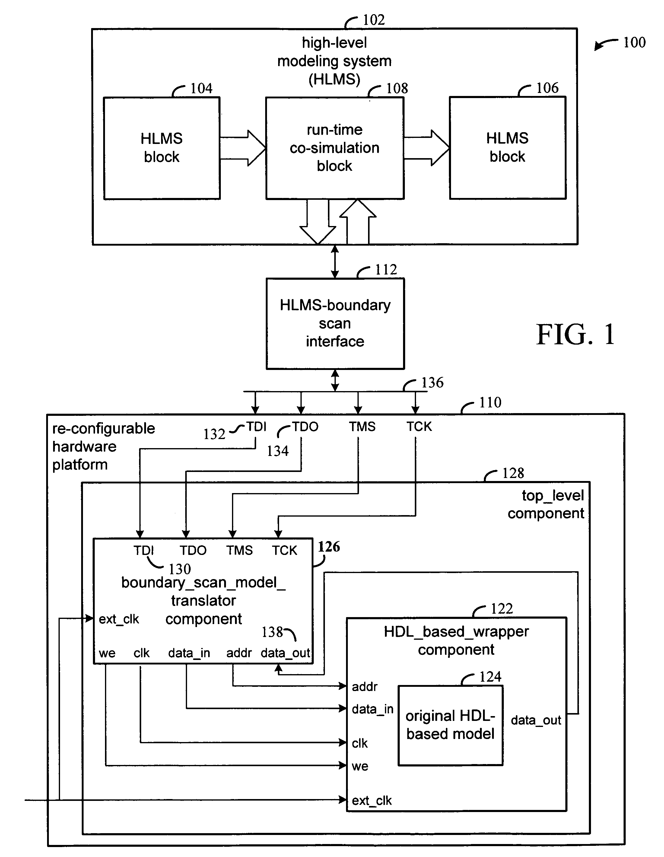
[0014]The various embodiments of the invention permit the same interface to be used for co-simulation on a reconfigurable hardware platform that may be hosted on any of a variety of board-level configurations. This is accomplished in an example embodiment through use of an interface that generally functions according to the Joint Test Action Group (JTAG) “Standard Test Access Port Boundary-Scan Architecture” (“boundary scan” for brevity). The boundary-scan architecture generally defines a 5-pin serial protocol for accessing and controlling the signal-levels of pins of a digital circuit. The broad adoption of this protocol makes its use in co-simulation attractive on a variety of platforms.

[0015]FIG. 1 is a functional block diagram of a system for co-simulating a model in accordance with various embodiments of the invention. The HLMS 102 hosts HLMS blocks 104 and 106 along with runtime co-simulation block 108. During co-simulation, output from HLMS block 104 is provided to co-simulat...


PUM


Abstract

Method and apparatus for interfacing a high-level modeling system (HLMS) with a reconfigurable hardware platform for co-simulation. In one embodiment a boundary-scan interface is coupled to the HLMS and is configured to translate HLMS-issued commands to signals generally compliant with a boundary-scan protocol, and translate signals generally compliant with a boundary-scan protocol to data compatible with the HLMS. A translator and a wrapper are implemented for configuration of the hardware platform. The translator translates between signals that generally compliant with the boundary-scan protocol and signals that are compliant with a second protocol. A component to be co-simulated is instantiated within the wrapper, and the wrapper transfers signals between the translator and the component.

Description

FIELD OF THE INVENTION[0001]The present invention generally relates to simulating high-level models of electronic circuits.BACKGROUND[0002]A high level modeling system (HLMS) is a software tool in which electronic designs can be described, simulated, and translated by machine into a design realization. An HLMS provides a higher level of abstraction for describing and simulating an electronic circuit than does a hardware description language (HDL) simulation environment such as the ModelSim environment from the Model Technology company. An HLMS generally provides a mathematical representation of signals as compared to standard logic vectors in a hardware description language (HDL). It is desirable for the high-level abstractions to be precisely correlated with the ultimate implementation representation, both in simulation semantics and in implementation. The Xilinx System Generator tool for DSP and the MathWorks' Simulink and MATLAB environments are example HLMS's in which such capab...

Claims


Application Information

Patent Timeline
IPC IPC(8): G06F9/455G06F17/50
CPCG06F17/5022G06F30/33
Inventor BALLAGH, JONATHAN B.SHIRAZI, NABEELBATTSON, CHRISTOPHER N.DARNALL, MICHAEL E.FROSS, BRADLEY K.
Owner XILINX INC
Why Eureka
Try Eureka