Orifice plate diffuser

Active Publication Date: 2007-03-06
CECO ENVIRONMENTAL IP INC
View PDF20 Cites 18 Cited by
  • Summary
  • Abstract
  • Description
  • Claims
  • Application Information

AI Technical Summary

Benefits of technology

[0008]The present invention broadly comprises a noise reducing device for diffusing a pressurized fluid stream, i.e., a gas, and generally comprises a housing having an inlet end and an outlet end. The inlet end and the outlet end each includes at least one orifice for passing a fluid therethrough. The inlet end orifice includes an inlet face and an outlet face and the inlet end orifice is operatively arranged to maintain a backpressure upstream of the inlet end orifice. The device further includes a diffusing p

Problems solved by technology

In most cases, high-pressure fluid releases cause the formation of turbulent jet flow, which results in the formation of excessive noise levels that can exceed over 120 decibels (dB).
The exposure to such excessive noise levels can result in permanent ear damage and/or permanent hearing loss.
Additiona

Method used


Image

  • Orifice plate diffuser
  • Orifice plate diffuser
  • Orifice plate diffuser

Examples


Embodiment Construction

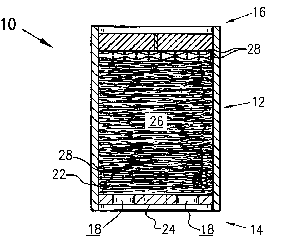
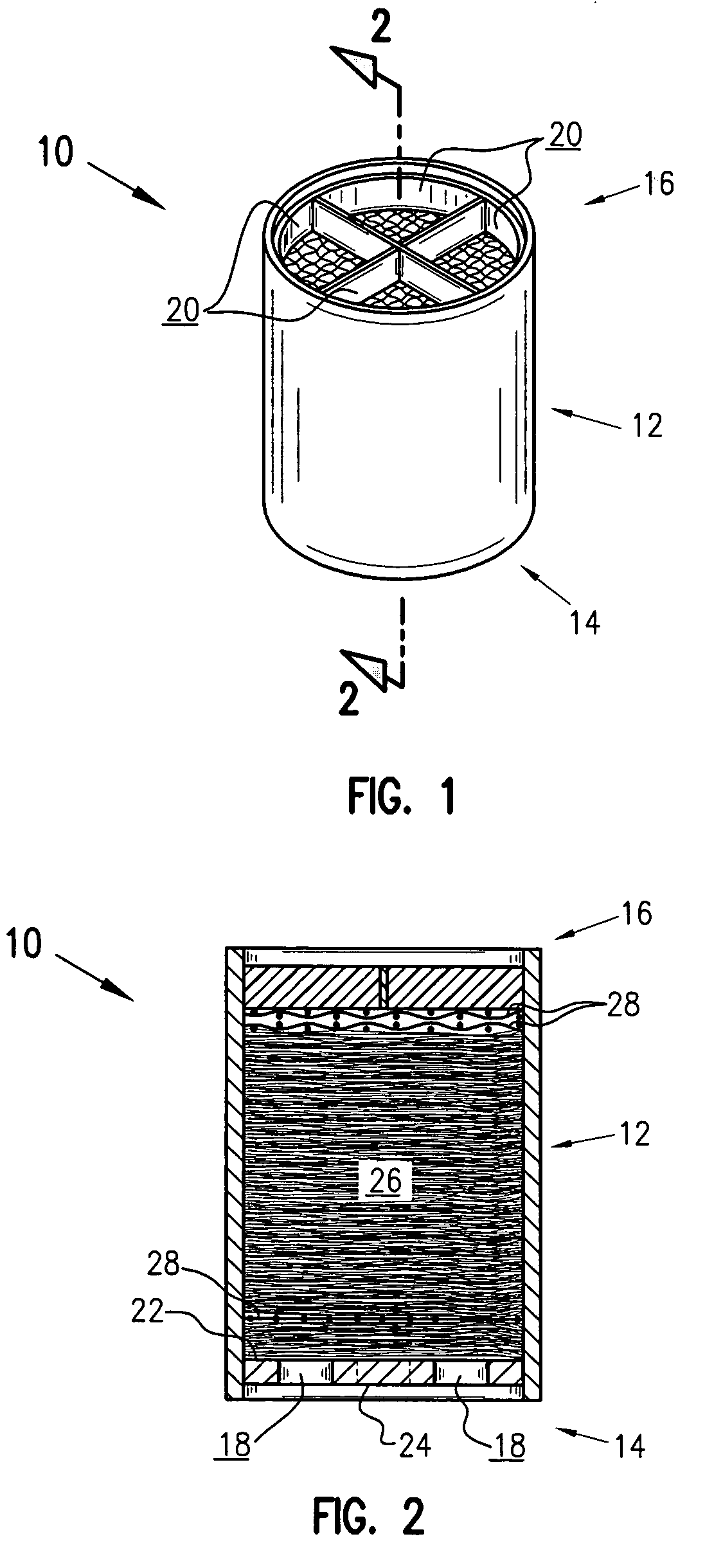
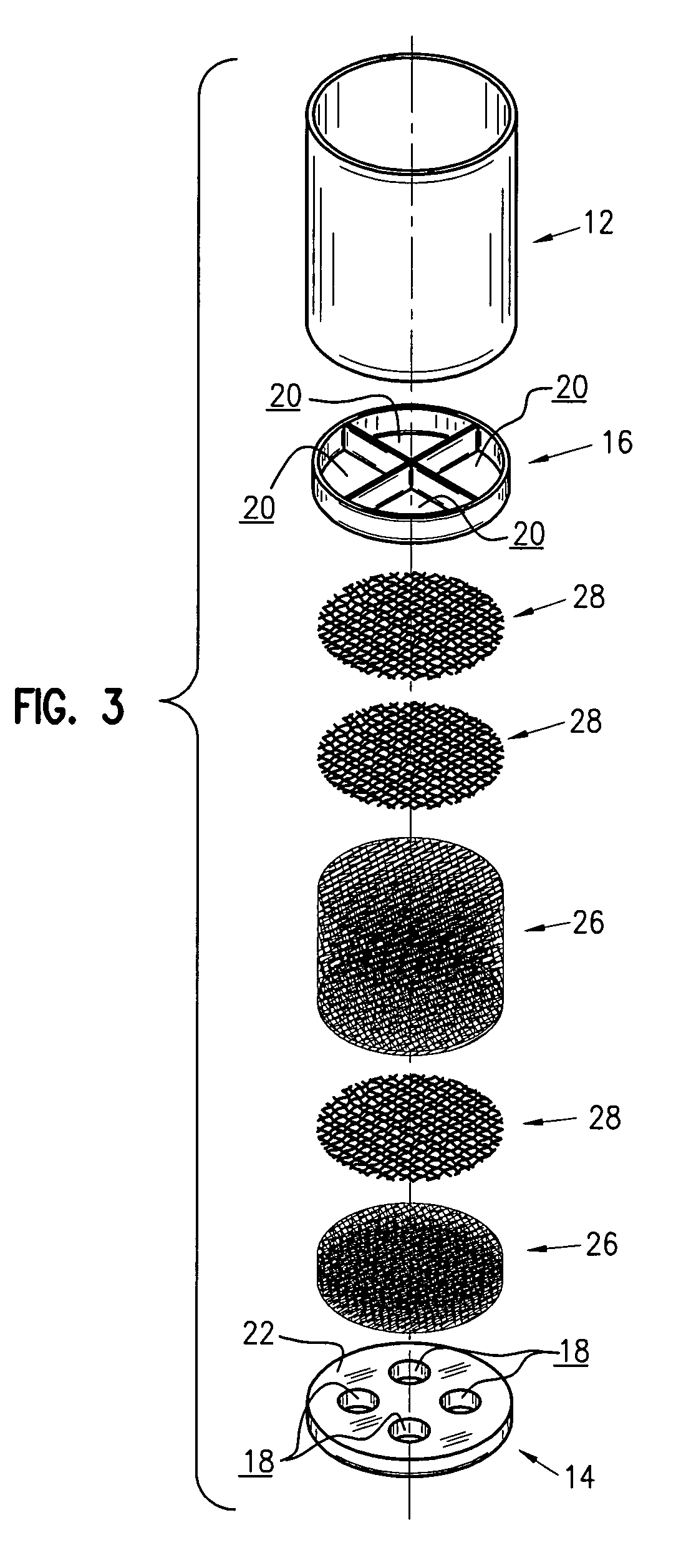
[0025]At the outset, it should be appreciated that like reference numbers on different drawing figures represent identical, or functionally similar, structural elements. It should also be appreciated that, while a number of different embodiments and variations of the present invention are shown in the various drawings, the invention as claimed is not intended to be limited to these specific embodiments as the claims define a broader invention that can take many different shapes and structures. In the detailed description and claims that follow, the term “fluid”, as in “fluid stream” is generally intended to connote a gas or a gas stream. In the detailed description and claims that follow, the phrase “diffusing pack material” is primarily intended to refer to a layered, knitted wire mesh, as described infra, but may also be used to refer to a stiffener means. i.e., a wire screen, or combinations thereof. Additionally, it should be appreciated by those having ordinary skill in the art...


PUM

PropertyMeasurementUnit
Pressureaaaaaaaaaa
Diameteraaaaaaaaaa
Diameteraaaaaaaaaa

Abstract

A noise reducing device for a pressurized fluid stream, i.e., a gas, includes a housing. An inlet end and an outlet end of the housing each have at least one orifice for passing a fluid therethrough. The inlet end orifice includes an inlet face and an outlet face and the inlet end orifice is configured for maintaining a backpressure upstream of the inlet end orifice. A diffusing pack material is disposed within the housing. One or more stiffeners may be disposed within the diffusing pack material to ensure that the diffusing pack material maintains contact with the outlet face of the inlet end orifice and/or to prevent the migration of the diffusing pack material within the housing, thereby maintaining a homogeneous distribution of the pack material.

Description

FIELD OF THE INVENTION[0001]The present invention relates generally to acoustical silencers, and more particularly, to devices for minimizing the incidence of formation of acoustic waves in high-pressure fluid streams.BACKGROUND OF THE INVENTION[0002]Many industrial processes require the release of high-pressure fluids to the atmosphere. The high-pressure fluids released typically comprise steam and gases that are expelled through vent or blow down systems of steam turbines, steam piping systems, and natural gas storage and compressor stations. Vent systems are typically characterized by a relatively constant flow of pressurized gas whereas blowdown systems are characterized by the release of fixed volumes of gas. Vent and blowdown systems can range in diameter from only a few inches to many feet and may vary in length from a few feet to upwards of forty feet or more. In most cases, high-pressure fluid releases cause the formation of turbulent jet flow, which results in the formatio...

Claims


Application Information

Patent Timeline
IPC IPC(8): F15D1/02
CPCF01N1/082F02K1/827F01N2310/04F01N2310/14F05D2300/171F05D2220/31F05D2260/95F05D2260/96
Inventor STELL, JAMES DENNISWITT, STEPHEN ERIC
Owner CECO ENVIRONMENTAL IP INC
Why Eureka
Try Eureka