
Anti-rotation device and anti-rotation structure for a pipe and a connector

a technology of anti-rotation device and anti-rotation structure, which is applied in the direction of hose connection, pipe coupling, coupling, etc., can solve the problems of limited piping design freedom, deterioration of sealing property between the connector and the pipe, and worn pipes, so as to achieve easy verification or finding, and simple operation

Active Publication Date: 2007-03-06
SUMITOMO RIKO CO LTD
View PDF29 Cites 26 Cited by
  • Summary
  • Abstract
  • Description
  • Claims
  • Application Information

AI Technical Summary

Benefits of technology

[0016]A pipe connecting portion may be configured to be connected to the inserting side portion of the pipe while clipping and pressing the inserting side portion, namely an outer peripheral surface of the inserting side portion in anti-rotating relation. This configuration allows the pipe connecting portion to be connected to the inserting side portion of the pipe in anti-rotating relation, even if the inserting side portion is formed round or of circle in cross-section. In this configuration, there is no longer need that an outer peripheral surface of the inserting side portion of the pipe is modified in shape, for example, by providing flat regions on diametrically symmetrical positions thereon. Further, there is no longer need that the pipe and the pipe connecting portion should be circumferentially aligned prior to mounting of the anti-rotation device.
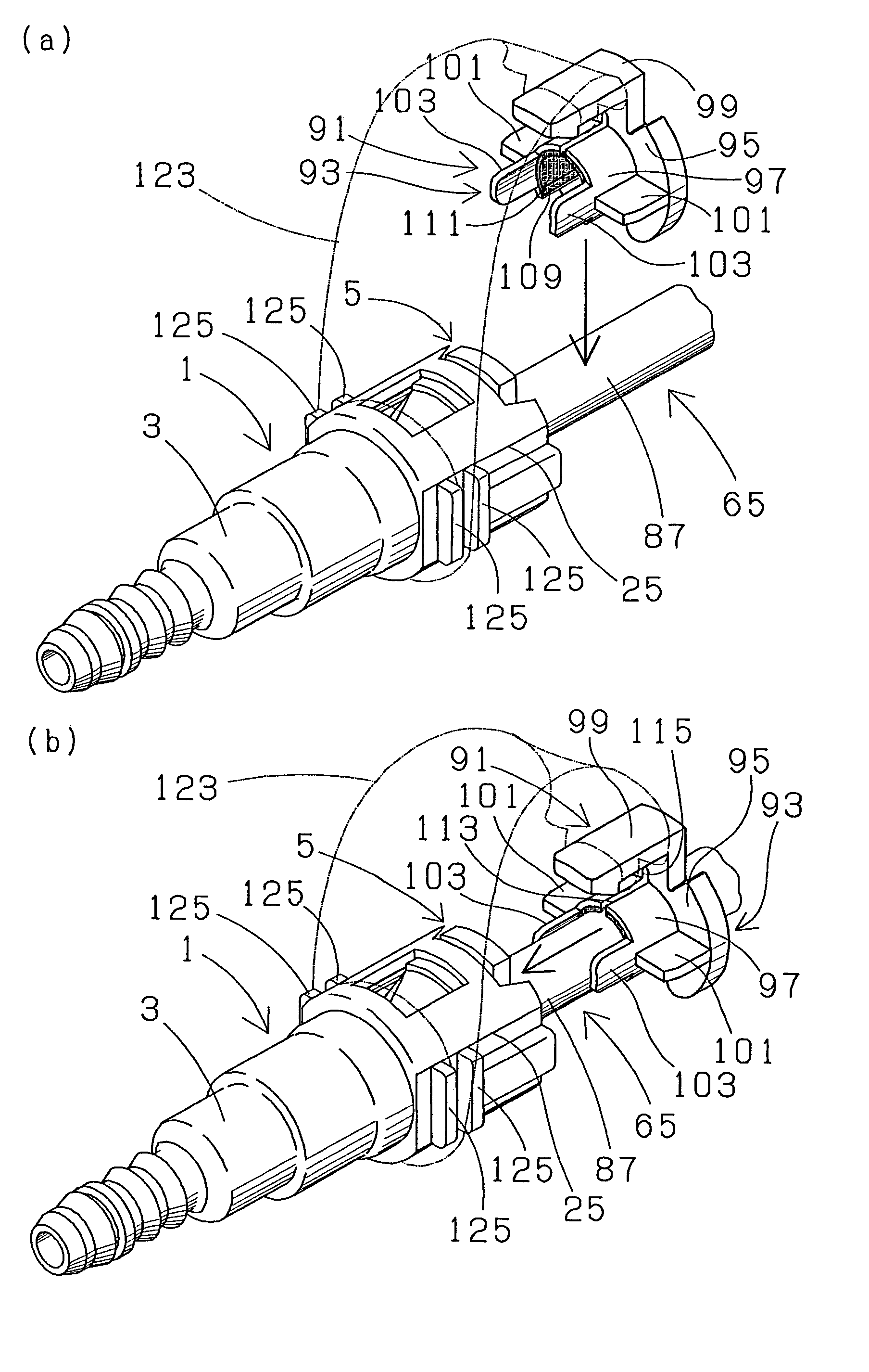
[0025]An anti-rotation device for a pipe and a connector according to the present invention may be adapted in order to restrain rotational movement of a pipe having a straight tubular inserting side portion and a connector having a connector housing provided with a connecting portion for a mating member to be connected with the pipe on one axial end of the connector housing and a retainer holding portion on the other axial end of the connector housing. A retainer is held in or by the retainer holding portion. The inserting side portion of the pipe is inserted in and connected to the connector housing through an opening of an opposite axial end thereof. The inserting side portion of the pipe engages with, for example, snap-engages with the retainer and thereby is connected to the connector housing. The retainer engages with an engagement window formed in the retainer holding portion and is thereby held by the retainer holding portion. The anti-rotation device for a pipe and a connector includes a pipe connecting portion which is connected to the inserting side portion of the pipe in anti-rotating relation, and a connector connecting portion which is constructed on or constructed integrally with the pipe connecting portion and is connected to the connector or the connector housing in anti-rotating relation. The connector connecting portion may be configured to be connected to the connector or the connector housing in anti-rotating relation by engagement with the engagement window of the retainer holding portion. If a retainer is provided in a connector for engagement with a pipe, in many cases, an engagement window is formed in a retainer holding portion of a connector housing and the retainer is held by the retainer holding portion via engagement with the engagement window. Therefore, if the connector connecting portion is designed to be connected to the connector housing in anti-rotating relation by utilizing the engagement window, it eliminates the need for modifying a design of a connector or a connector housing.

Problems solved by technology

Meanwhile, for example, when a resin tube connected to a connector is continued to a gasoline engine of an automobile, the connector or a connector housing constantly rotates at a small angle with respect to a pipe by vibration transmitted from the gasoline engine to the connector via the resin tube, and thereby a sealing member which is disposed between the connector or the connector housing and the pipe is worn and a sealing property is deteriorated between the connector and the pipe.
However, if an anti-rotation device as disclosed in the document 1 or document 2 is adapted, piping design freedom is limited as a connector joining portion should be arranged near a bent portion of a pipe.
It is troublesome to configure the bent portion on the pipe with such high bending accuracy.
Also, anti-rotation structure disclosed concretely in the document 3 or 4 does not have sufficient range of applicability as no independent anti-rotation device is applied.

Method used


Image

  • Anti-rotation device and anti-rotation structure for a pipe and a connector
  • Anti-rotation device and anti-rotation structure for a pipe and a connector
  • Anti-rotation device and anti-rotation structure for a pipe and a connector

Examples


Embodiment Construction

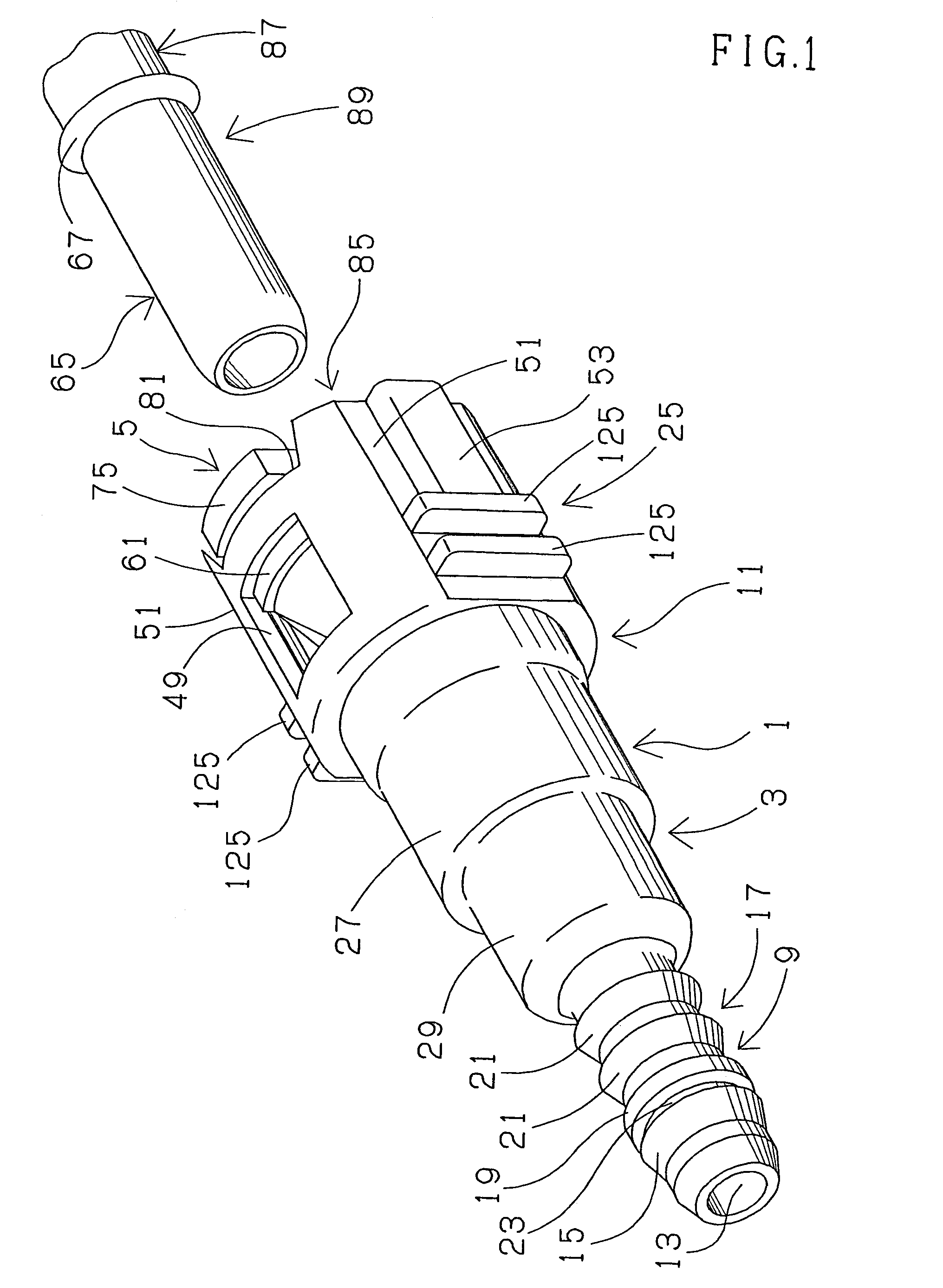
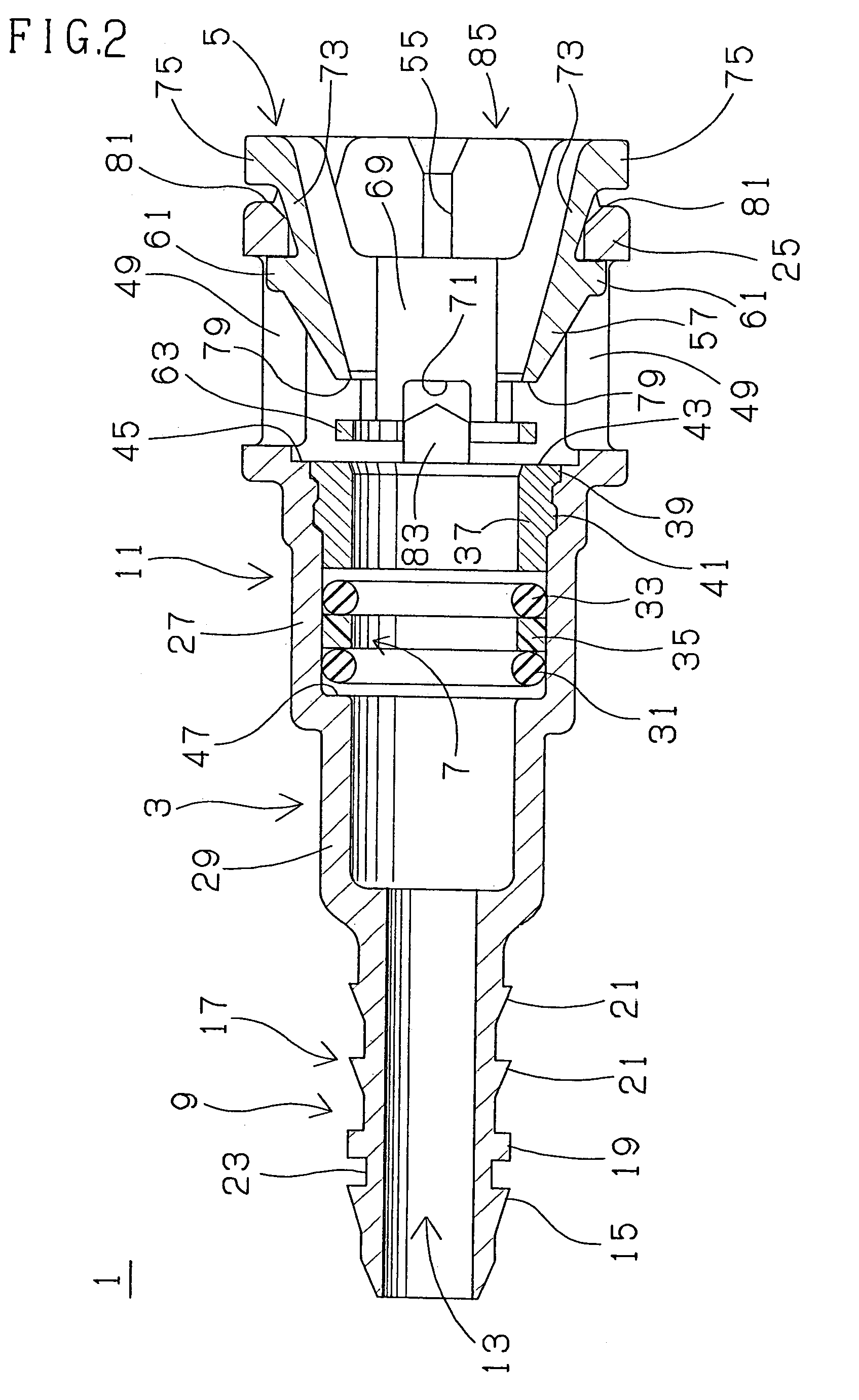
[0082]A first anti-rotation structure for a pipe and a connector is explained with reference to FIGS. 1 to 13. A first quick connector 1, which is adapted for assembly in a gasoline fuel piping of an automobile and adapted in the first anti-rotation structure comprises a tubular connector housing 3, a generally annular retainer 5 and sealing means 7 as well shown in FIGS. 1 and 2. The connector housing 3 made of glass fiber reinforced polyamide (PA•GF), integrally comprises a cylindrical resin tube connecting portion 9 on one axial end of the connector housing and a generally cylindrical pipe inserting portion 11 on the other axial end of the connector housing, and is provided with a through-bore 13 through from one axial end to an opposite axial end thereof. The resin tube connecting portion 9 comprises one axial side portion 15 having an outer peripheral surface generally expanding gently in diameter toward the other axial end, and an opposite axial side portion 17 having an outer...


PUM


Abstract

Anti-rotation device for a pipe and a connector has a pipe connecting portion and a connector connecting portion constructed integrally on the pipe connecting portion. The anti-rotation device is mounted on the pipe and the connector while the pipe connecting portion clips a straight tubular inserting side portion of the pipe in anti-rotating relation and the connector connecting portion is connected to the connector in anti-rotating relation. Thereby the pipe is connected to the connector in anti-rotating relation.

Description

BACKGROUND OF THE INVENTION[0001]The present invention relates to an anti-rotation device and anti-rotation structure for a pipe and a connector to restrain or prevent a connector, for example, which is adapted for assembly in a gasoline fuel piping of an automobile, from relatively rotating with respect to a pipe which is inserted in and connected to the connector.[0002]In a gasoline fuel piping for an automobile, a connector is used for connecting a pipe and a resin tube as a mating member. For example, the connector comprises a tubular connector housing and a retainer. The connector housing is formed with a tube connecting portion on one axial side and a retainer holding portion on the other axial end of the connector housing. The retainer is received or held by the retainer holding portion. In this structure, a resin tube is fitted to the tube connecting portion, the pipe is inserted in the connector housing through an opening of an opposite axial end of the connector housing or...

Claims


Application Information

Patent Timeline
IPC IPC(8): F16L37/00F02M37/00F02M55/02F16L37/084F16L37/12
CPCF16L37/0847F16L37/0987F16L2201/10
Inventor TAKAYANAGI, AKIRAINOUE, TOMOKI
Owner SUMITOMO RIKO CO LTD
Learn More