Imaging optical system
a technology of optical system and image plane, which is applied in the field of imaging system improvement, can solve the problems of affecting the image plane, and unable to ensure the simultaneousity of the whole range of the aperture of the shutter itsel
- Summary
- Abstract
- Description
- Claims
- Application Information
AI Technical Summary
Benefits of technology
Problems solved by technology
Method used
Image
Examples
example 1
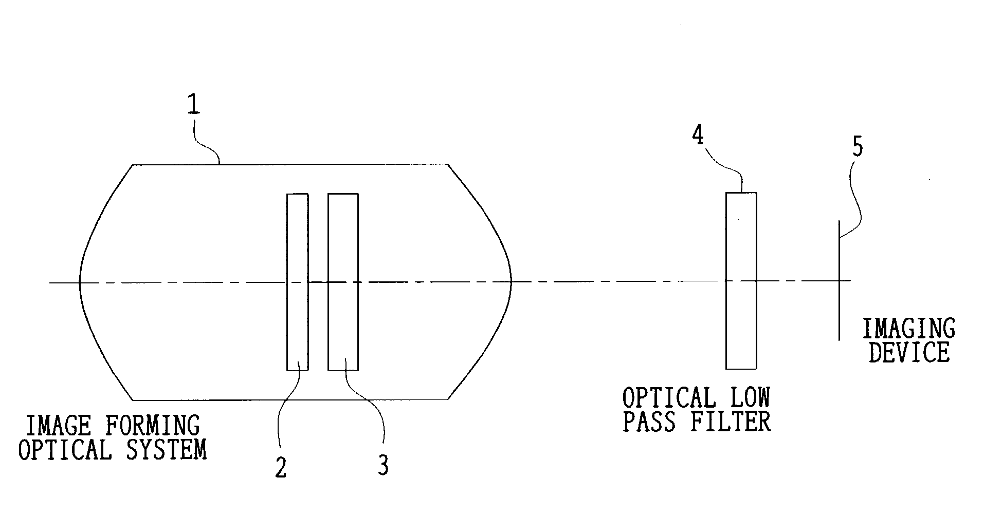
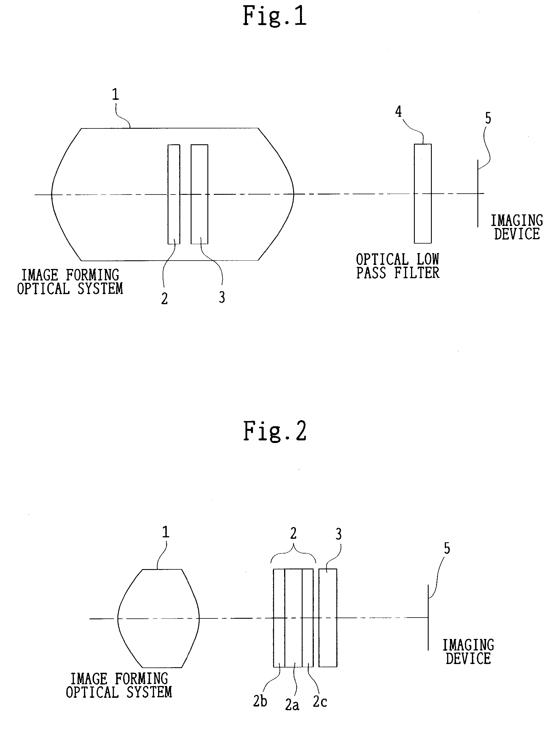
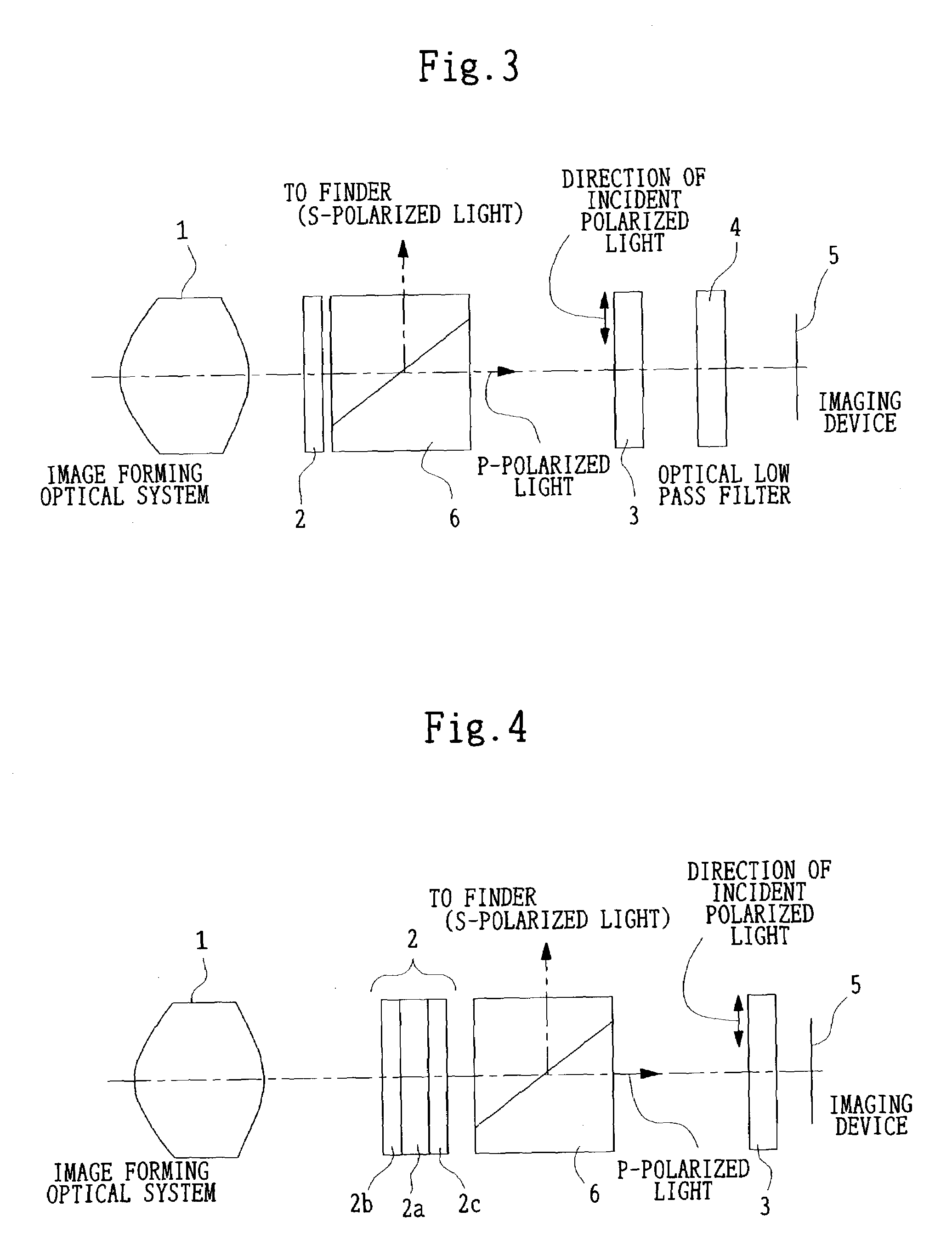
[0055]A zoom lens system including, in order from the object side, a first lens unit and a lens unit P with positive refracting power. A zoom lens system in which when the magnification is changed from the wide-angle position to the telephoto position, the lens unit P is moved integrally with the aperture stop toward only the object side. (In particular, an effective optical system is of the type that the first lens unit has a reflecting optical element for bending the optical path. The above construction is also effective for the optical system of the type that the lens unit P approaches the first lens unit at the telephoto position to such an extent that a member for adjusting the amount of light is not included between them.)
2. An optical system in which it is difficult to ensure space for a lens shutter mechanism in the proximity of the stop.
example 2
[0056]A zoom lens system including, in order from the object side, a first lens unit, a second lens unit moved when the magnification is changed, an aperture stop, and a lens unit Q moved when the magnification is changed. A zoom lens system in which when the magnification is changed from the wide-angle position to the telephoto position, at least one of the second lens unit and the lens unit Q is moved toward only one of the object side and the image side. (In this case also, an effective optical system is of the type that the first lens unit has a reflecting optical element for bending the optical path. This construction is also effective for the optical system of the type that the lens unit Q approaches the stop at the telephoto position to such an extent that a member for adjusting the amount of light is not included between them.)
3. An optical system which has the problem of dust adhesion to the image plane due to the mechanical drive of a focal-plane shutter.
example 3
[0057]An optical system in which a back focal distance is long as in the imaging optical system of the single-lens reflex camera. For example, an optical system for cameras satisfying a condition: Fb≧1.8·fw, where Fb is an equivalent-air medium length of a distance from the most image-side vertex of the last lens component with refracting power to the imaging plane and fw is the focal length of the zoom lens at the wide-angle position.
[0058]In the optical system of the type described in Item 1, the shutter stop with physical properties can be fixed at any proper position. By doing so, the inside diameter of the aperture stop moved when the magnification is changed can be kept constant. Consequently, the stop mechanism becomes unnecessary and a large mechanism including the shutter need not be moved. The shutter stop with physical properties need not necessarily be located in the proximity of the aperture stop as mentioned above. Therefore, the above construction is also effective fo...
PUM
| Property | Measurement | Unit |
|---|---|---|
| transmittance | aaaaa | aaaaa |
| reflectance | aaaaa | aaaaa |
| angle | aaaaa | aaaaa |
Abstract
Description
Claims
Application Information
 - R&D
- Intellectual Property
- Life Sciences
- Materials
- Tech Scout
- Unparalleled Data Quality
- Higher Quality Content
- 60% Fewer Hallucinations
Browse by: Latest US Patents, China's latest patents, Technical Efficacy Thesaurus, Application Domain, Technology Topic, Popular Technical Reports.
© 2025 PatSnap. All rights reserved.Legal|Privacy policy|Modern Slavery Act Transparency Statement|Sitemap|About US| Contact US: help@patsnap.com


