
Padding machine and method of use

a technology of adding machine and a coating machine, which is applied in the direction of mechanical machines/dredgers, grain treatment, mechanical apparatus, etc., can solve the problems of destroying the spoil back into the trench, destroying the pipe or its protective cover or coating, and long expanses of pipe underground, etc., to achieve the effect of improving the operability of the device and operating effectively

Inactive Publication Date: 2007-03-06
BARNES TOMMY
View PDF33 Cites 20 Cited by
  • Summary
  • Abstract
  • Description
  • Claims
  • Application Information

AI Technical Summary

Benefits of technology

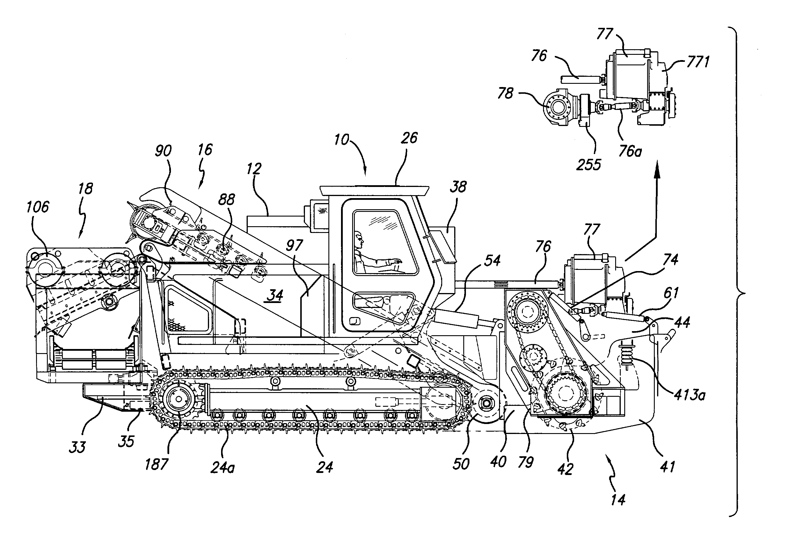
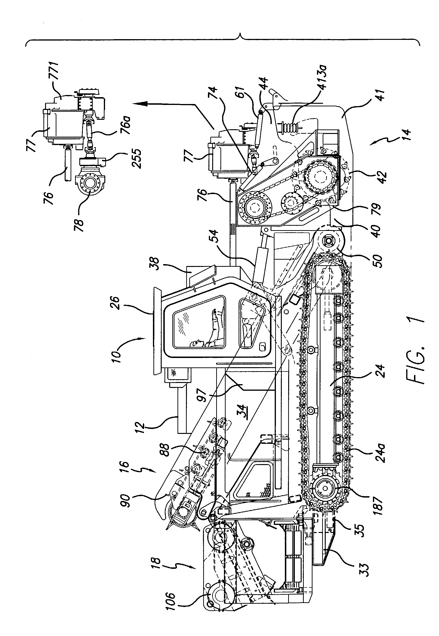
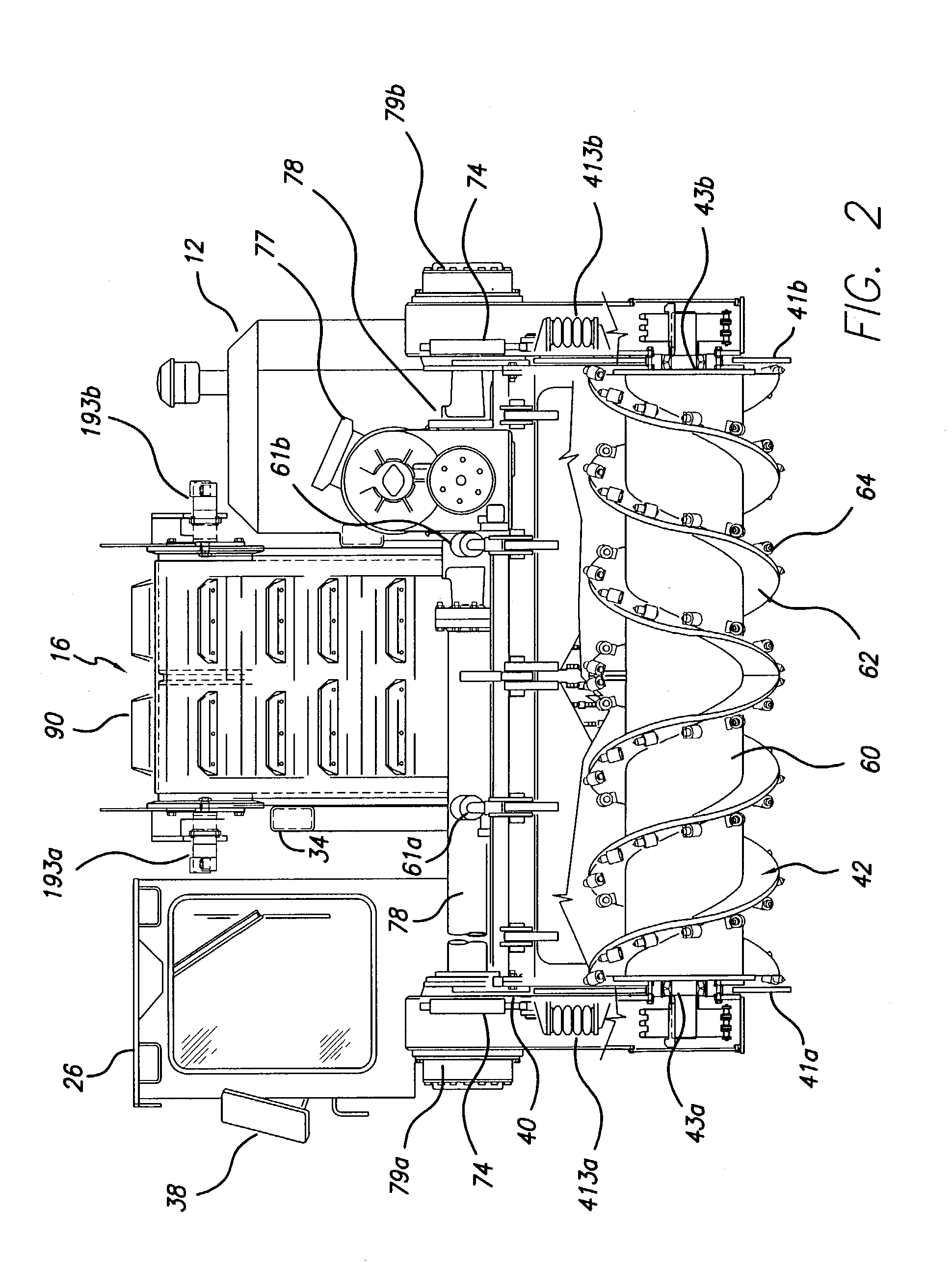
[0024]First, the padding machine of this invention replaces the usual front feed or guide assembly which the prior art machines use to feed or guide the spoil to the up conveyor with a digging auger that is preferably mechanically (as opposed to hydraulically) operated, and a breaker bar assembly in front of the up conveyor. The preferred front digging auger is the type now used on road planers (such as the Caterpillar PR1000 Cold Planer). It has carbide teeth around the periphery of its flights such that the auger simultaneously digs and conveys the dug material to the center of the auger where it is fed to the up conveyor. Therefore, the front digging auger of this invention provides the dual role of digging into the spoil pile (and into the earth under the spoil pile if desired) and guiding or feeding the spoil (and any dug earth) onto the up conveyor. This provides much improved consumption of the spoil pile, regardless of the condition of the pile (such as being partially frozen due to freezing ambient temperatures). It also provides a crushing capability in that the digging auger (which will operate at high revolutions per minute thus providing significant torque) starts to break the aggregate material in the spoil pile down to fines immediately. Large aggregate material that is not immediately broken into its component parts will be crushed between the auger and the breaker bar, or held against the breaker bar and systematically ground into smaller fines by the continuous grinding action of the carbide teeth on the auger.
[0034]Ninth, the machine is equipped with a heating system that allows it to operate effectively in freezing temperatures.

Problems solved by technology

But, the process of putting long expanses of pipe underground creates unique problems.
Therefore, it has long been known that simply bulldozing the spoil back into the trench was not acceptable.
Because the spoil will often include rocks or other aggregate material of one size or another, simply bulldozing the spoil bank back into the trench may damage the pipe or its protective cover or coating as the rocks fall directly on it.
Also, the rocks or aggregate material may create an unwanted and dangerous pressure point on the pipe.
Or they may “bridge” in the trench, preventing the backfill material from flowing under and around the pipe, thus creating an unevenly supported pipe that might be more susceptible to leaking or, worst, rupture.
Lastly, just bulldozing the spoil back into the trench can leave an unsightly job site.
This proved inadequate for reasons of cost primarily.
As in almost all, if not all, competitive commercial activities, cost is an incredibly important factor in this industry.
These large, pipe-laying projects can cost millions, if not ten's or hundred's of millions of dollars.
Ways to improve the padding process and to do so at less cost are constantly being explored, and it is not surprising that trucking in the fine padding material was not acceptable for very long.
As can be appreciated, if the padding machine must stop, reverse direction, and then re-pad an area, average forward speed is adversely affected.
The auger, however, has no effective digging or crushing capability.
While these existing machines are all functional to a degree, none of them provides the advantages obtained by the machine herein disclosed and described.
None of the prior art machines provides both effective digging and crushing capability by incorporating a true digging auger (i.e., one that is preferably mechanically driven rather than being hydraulically driven) previously used in road planers and the like, that not only acts to deliver the spoil to the up-conveyor as in prior art machines, but also digs and crushes to produce a higher percentage of fines.
Those dirt clods are simply passed through the machine, thus diminishing the production of fines instead of enhancing it.
None of the prior art machines can effectively pad pipe at a 45 degree up-grade; none of the prior art machines constantly monitors the amount of padding so that the operator can ensure that enough but not too much padding is being added to the trench; none of the prior art machines provides truly enhanced operational control; none of the prior art machines can be effectively used in freezing conditions; none of the prior art machines provide screens that can be effectively used with wet and grassy spoil; and none of the prior art machines provides means for effective dust control or for padding in freezing conditions.

Method used


Image

  • Padding machine and method of use
  • Padding machine and method of use
  • Padding machine and method of use

Examples


Embodiment Construction

[0062]As best seen in FIG. 1, the padding machine hereinafter described has the following major components: the vehicle 10, the engine 12, the front digging auger and frame assembly 14, the up conveyor assembly 16, the screening assembly 18, and the cross-pass conveyor assembly 20.

[0063]The vehicle 10 comprises a main frame 22, a track assembly 24 having tracks 24a and 24b, and an operator's cab 26. As best seen in FIGS. 4 and 17, the main frame 22 comprises track cross members 30 having a central pivot point 32 and a box frame 34 that is pivotally attached to the cross members 30 at pivot point 32, and which will provide the main support structure for the other components (such as the up conveyor and screening assemblies). A pair of front and back hydraulic arms 36a and b are attached between the box frame 34 and the cross members 30 and act to maintain the box frame 34 (and hence the component parts attached thereto) level as the vehicle traverses slopes and as the tracks independ...


PUM


Abstract

An integrated padding machine that incorporates a front digging auger that is preferably mechanically as opposed to hydraulically powered, which in conjunction with a breaker bar assembly provides for digging and crushing capabilities, and that incorporates several other improvements and advances, including screen and cross-pass conveyor level control, a real-time padding level monitoring system, and an assistant's control module, improved controls, dust control, and cold weather padding, and methods of using the machine.

Description

FIELD OF THE INVENTION[0001]This invention relates to machines and method of their use for processing the already-excavated material from a trench, and returning the fine material extracted therefrom back into the trench to pad the pipe before the trench is completely refilled. In particular, this invention relates to a padding machine that incorporates digging and crushing capabilities among many other improvements, and thus can be used to more efficiently and expeditiously process the excavated material, and to do so effectively in varying terrains and under varying soil and climatic conditions.BACKGROUND[0002]Laying pipe underground uses the three basic steps that are involved in burying anything in the ground—1) dig the hole; 2) put the thing to be buried in the hole; and 3) file the hole back up again. But, the process of putting long expanses of pipe underground creates unique problems. These projects can involve trenches that are up to several feet deep and wide, and extend f...

Claims


Application Information

Patent Timeline
IPC IPC(8): E02F5/22E02F3/20E02F7/02E02F7/06E02F9/02E02F9/20
CPCE02F3/20E02F5/226E02F7/02E02F9/205E02F9/028E02F9/2004E02F7/06
Inventor BARNES, TOMMY
Owner BARNES TOMMY
Learn More