
Vapor phase decontamination of containers

a technology of vapor phase and container, which is applied in the field of sterilization arts, can solve the problems of unsatisfactory changes, liquid hydrogen peroxide sterilization and condensed vapor sterilization systems are currently unable to meet these stringent regulations, and the recontamination of sterilized containers is likely to occur, and achieves a large throughput of containers to be decontaminated, the effect of high output of vaporized hydrogen peroxid

Active Publication Date: 2007-03-06
AMERICAN STERILIZER CO
View PDF38 Cites 75 Cited by
  • Summary
  • Abstract
  • Description
  • Claims
  • Application Information

AI Technical Summary

Benefits of technology

[0014]One advantage of at least one embodiment of the present invention is that a high output of vaporized hydrogen peroxide is achieved.
[0015]Another advantage of at least one embodiment of the present invention is that it enables a large throughput of containers to be decontaminated.

Problems solved by technology

Trace amounts of hydrogen peroxide on food packaging can affect the flavor of the product or result in other undesirable changes, such as a change in the color of the product.
Liquid hydrogen peroxide sterilization and condensed vapor sterilization systems are currently unable to meet these stringent regulations without extensive post sterilization processing.
However, unless a high purity water supply can be assured, which tends to be costly, recontamination of the sterilized containers is likely to occur.
Heat, for example a 400° C. drying phase, has also been used to attempt to reduce the residual level, but adds considerably to processing time and cost and cannot generally be used with thin-walled plastic bottles.
Additionally, current vaporization systems are unable to handle the latest, high speed bottling plants.
The capacity of current drip-feed vaporizers is limited because the carrier gas flow and vaporization step tend to reduce the temperature of the heated plate.
Another solution is to employ a multiple firing vaporizer, in which different areas of a vaporizer plate are sequentially supplied with the hydrogen peroxide solution Although helpful, the larger vaporizer still suffers from concentration variations and condensation concerns.
However, the use of multiple vaporizers adds to the cost of the system and requires careful monitoring to ensure that each vaporizer is performing efficiently.

Method used


Image

  • Vapor phase decontamination of containers
  • Vapor phase decontamination of containers
  • Vapor phase decontamination of containers

Examples


Embodiment Construction

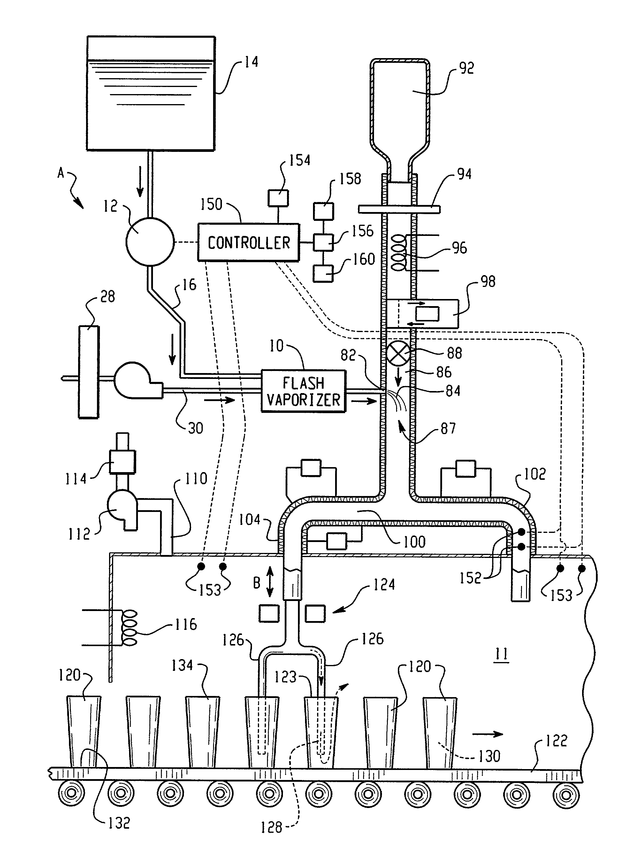
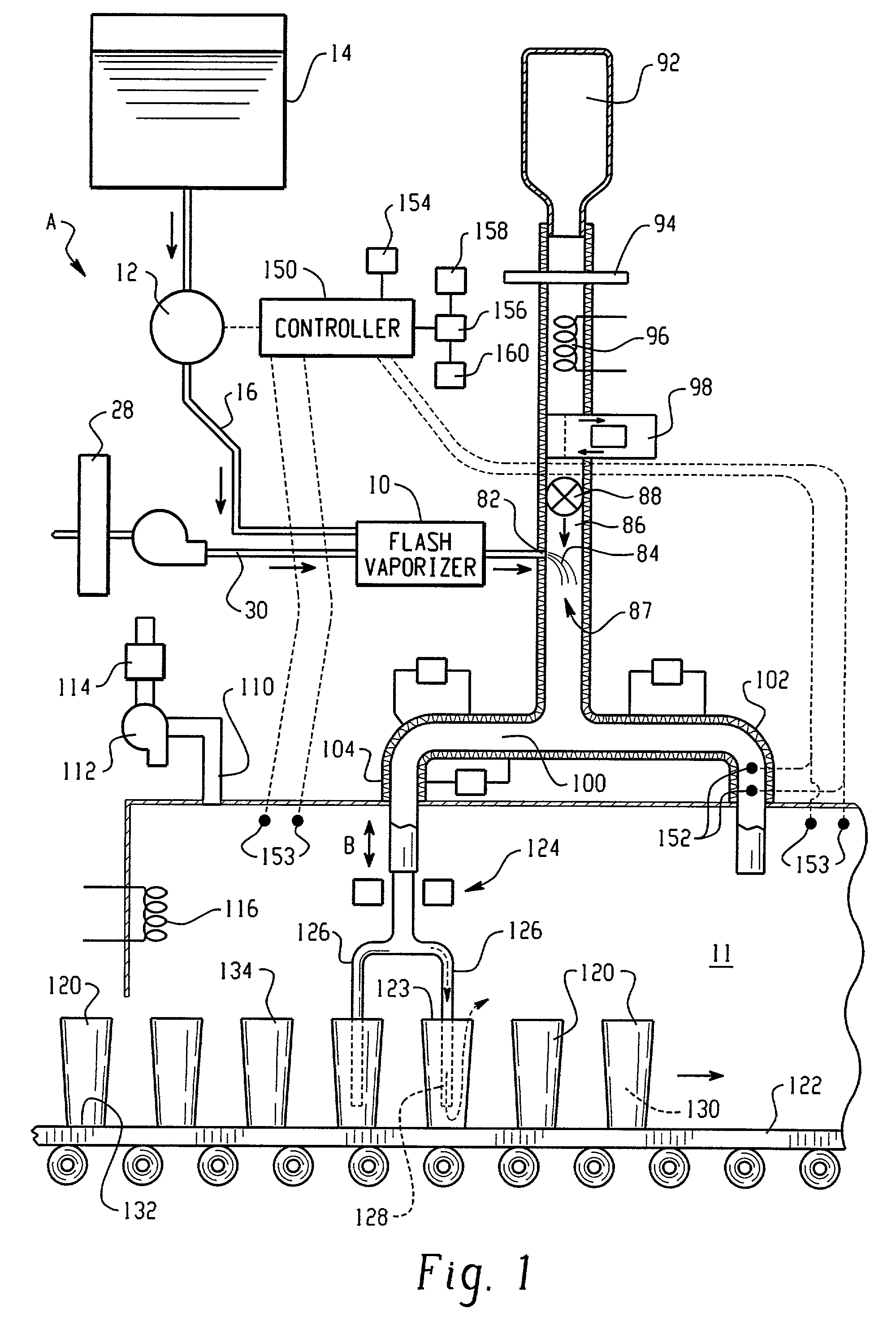
[0031]With reference to FIG. 1, a system for supplying vapor hydrogen peroxide to an aseptic filling plant A includes a flash vaporizer 10, which converts liquid hydrogen peroxide to vaporized hydrogen peroxide. The vapor produced is then injected into a carrier gas and carried in the gas to a site, such as a decontamination tunnel 11, where the vapor is to be used. Alternatively, the vapor is drawn under a vacuum to the tunnel 11. The vaporizer allows for continuous production of vapor hydrogen peroxide for microbial decontamination of the decontamination tunnel and its contents. While the invention is described with particular reference to hydrogen peroxide, it will be appreciated that the system is also applicable to vaporization of other solutions and pure liquids, such as the formation of peracetic acid vapor from a peracetic acid solution.

[0032]The term “microbial decontamination” and similar terms, as used herein, encompass sterilization, disinfection, and lesser forms of ant...


PUM

PropertyMeasurementUnit
Fractionaaaaaaaaaa
Angleaaaaaaaaaa
Angleaaaaaaaaaa

Abstract

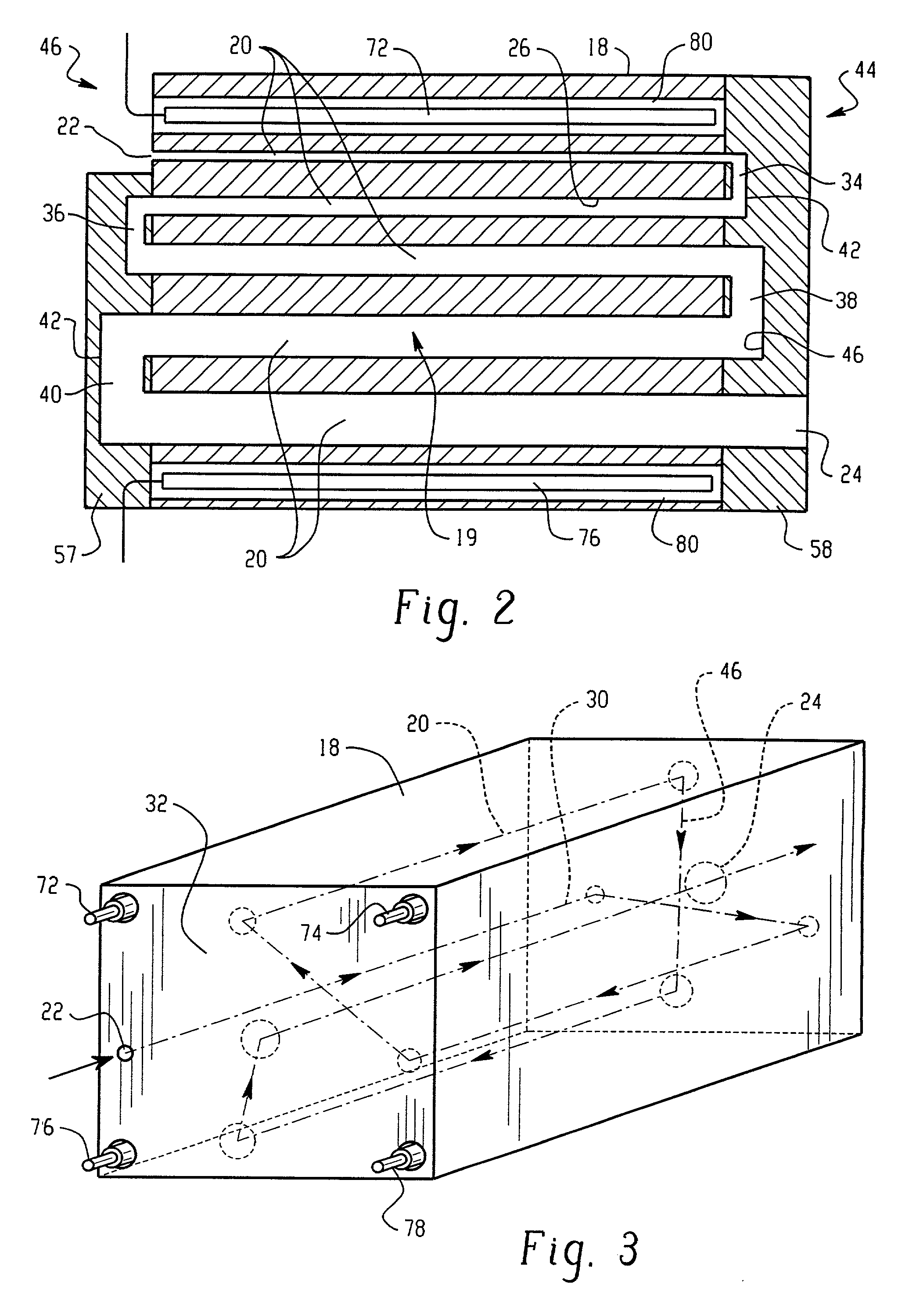
A flash vapor generator (10) provides a constant flow of vaporized hydrogen peroxide for rapidly sterilizing a large decontamination tunnel (11) with a high container throughput. The vaporizer includes a heated block which defines an interior bore or bores. The conditions within the decontamination tunnel are carefully monitored to avoid condensation of the vapor while maintaining the vapor as close as possible to the saturation limit.

Description

[0001]This application claims the priority of U.S. Provisional Application Ser. No. 60 / 269,549, filed Feb. 16, 2001, and U.S. Application Ser. No. 60 / 269,659, filed Feb. 16, 2001.BACKGROUND OF THE INVENTION[0002]The present invention relates to the sterilization arts. It finds particular application in conjunction with hydrogen peroxide vaporization systems for the sterilization of packaging containers, and will be described with particular reference thereto. It should be appreciated, however, that the invention is also applicable to other chemical vaporization systems such as peracetic acid vaporization systems.[0003]Packaging plants, which use filling lines for filling containers with beverages, food, pharmaceuticals, and the like, are moving to aseptic processing techniques to ensure that the finished product is free of hazardous microorganisms and to maintain the shelf life of the product. As a part of the aseptic process, the containers are microbially decontaminated prior to f...

Claims


Application Information

Patent Timeline
IPC IPC(8): A61L9/00A61L2/18A61L2/20B65B55/02B65B55/10B67C7/00
CPCA61L2/186A61L2/208B67C7/0073B65B55/025B65B55/10A61L2202/23
Inventor ZELINA, FRANCIS J.MCDONNELL, GERALD E.HILL, AARON L.MIELNIK, THADDEUSMCVEY, IAIN F.BUCZYNSKI, PETER J.
Owner AMERICAN STERILIZER CO
Learn More