
Device and method for detection and identification of biological agents

Active Publication Date: 2007-03-06
LEIDOS
View PDF143 Cites 79 Cited by
  • Summary
  • Abstract
  • Description
  • Claims
  • Application Information

AI Technical Summary

Benefits of technology

[0015]The conventional methods neither achieve nor teach methods or devices to meet the above-mentioned criteria for a biosensor. Therefore, it is an object of this invention to provide a compact, inexpensive, rugged and portable biosensor that can continuously monitor the environment for detection and identification of hazardous biological agents.
[0028]A first embodiment of the present invention describes a method of determining a target agent in an environment comprising the steps of obtaining a first sample from the environment and introducing the first sample to at least one detection module. The first sample is then filtered through at least a first filter and a second filter comprising at least one detection module, wherein the first filter contains at least one detection molecule for the target agent and the second filter contains no detection molecules for the target agent. An optical property is measured from the first filter and the second filter after filtering the first sample there through. Comparing the measured optical property of the first filter to the measured optical property of the second filter assists in determining the presence of the target agent.

Problems solved by technology

Although standoff sensors, such as lidar, provide some remote sensing of the release of agents, they cannot identify particular agents.
These detectors do not, however, provide the specificity to identify the agents present.
Additionally, these devices are complex and bulky.
Other devices capable of agent detection and identification, e.g., mass spectrometry, are expensive and not easily portable.
These devices take a considerable amount of time to identify the agent(s).
Unfortunately, these techniques are not readily amenable to providing continuous, always-on monitoring of the environment.
Moreover, these techniques are not reagentless; they normally require additional chemistry to add chromophores or fluorescing agents for detection and identification by color change or fluorescence.

Method used


Image

  • Device and method for detection and identification of biological agents
  • Device and method for detection and identification of biological agents
  • Device and method for detection and identification of biological agents

Examples


Embodiment Construction

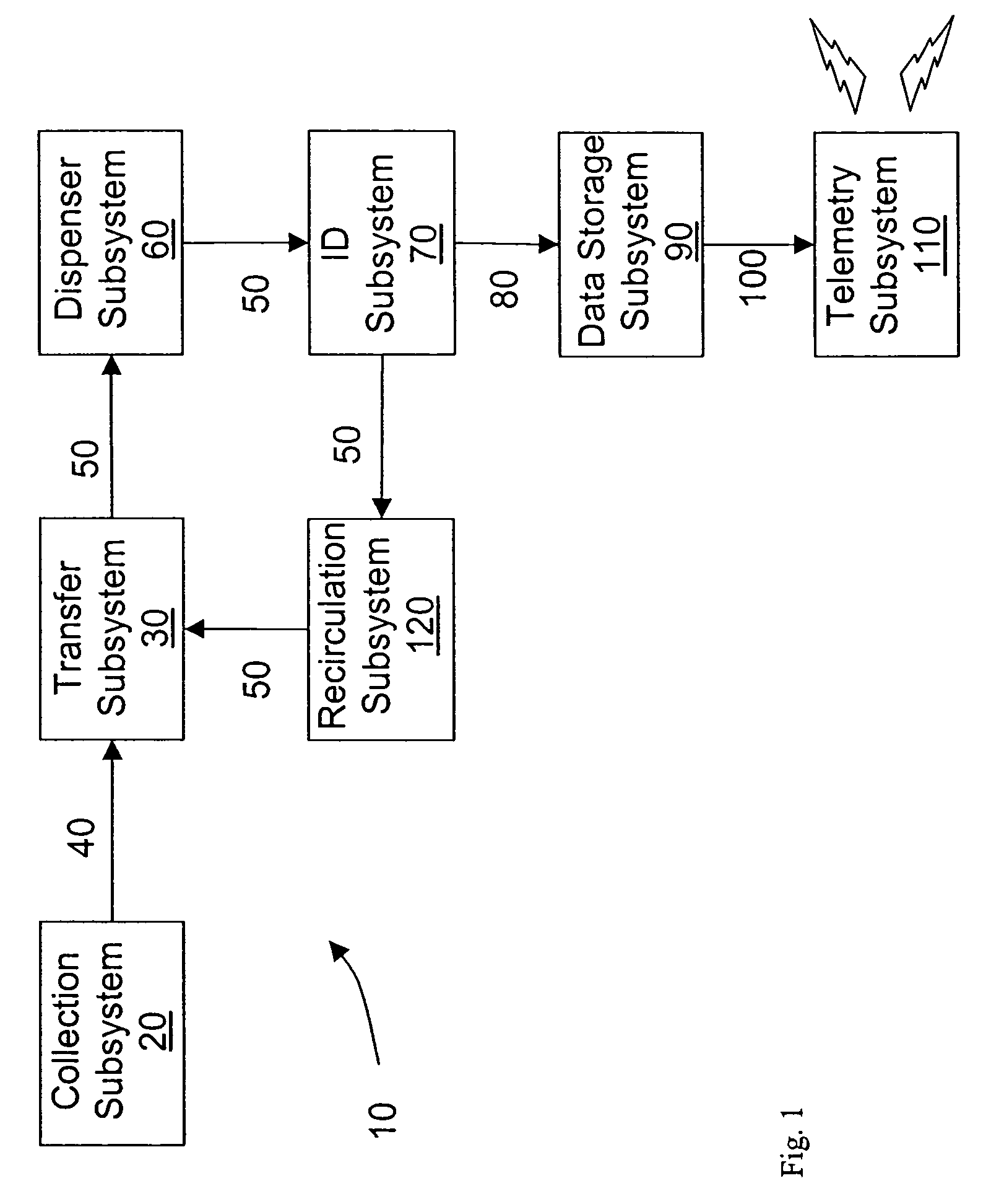
[0057]In an embodiment of the present invention as shown in FIG. 1, a biological and chemical target agent sensor 10 has a sample collection subsystem 20 that continuously draws samples of air, water, and soil from the environment. A transfer subsystem 30 transfers the sample 40 from the collection subsystem 20 to working fluid 50. A dispenser subsystem 60 dispenses the working fluid 50 containing the sample into a detector module array (“DMA”) of a detection / identification (hereafter “ID”) subsystem 70.

[0058]The dual-function ID subsystem 70 sends the sample data from the DMA through an electronic signal 80 to a data storage subsystem 90. Data storage subsystem 90 obtains and continuously compiles data from the DMA. The data within data storage subsystem 90 may either be accessed directly or may be sent via an appropriate transmission system, such as telemetry subsystem 110, for recording and analysis. The transmission system may send data at pre-selected intervals in batch format ...


PUM


Abstract

A method of sensing an environmental agent, comprising obtaining a sample from the environment and transferring the sample into the working fluid for dispensation to a detection module. The sample and working fluid mixture is filtered through a porous polymer Bragg grating. By comparing the refractive index of the grating with the mixture to the refractive index of a grating without the sample, a difference in the refractive index aids in the identification of a hazardous agent in the environment. The sensor also acts as a chemical filter by trapping specific target agents by a highly specific reaction with a conjugate molecule. Recirculation of the working fluid throughout the system provides a sensor that is “always on.”

Description

CROSS-REFERENCE TO RELATED APPLICATIONS[0001]“This application is a divisional application of and claims priority to and incorporates by reference in its entirety application Ser. No. 10 / 614,188 entitled. “DEVICE AND METHOD FOR DETECTION AND IDENTIFICATION OF BIOLOGICAL AGENTS,” filed Jul. 8, 2003, which application claims priority to and incorporates by reference in its entirety U.S. Provisional patent Application No. 60 / 406,665 entitled “METHOD AND APPARAUS FOR DETECTION AND ANALYSIS” filed Aug. 29, 2002.”BACKGROUND OF THE INVENTION[0002]1. Field of the Invention[0003]The present invention relates generally to a sensor system, and more specifically to a sensor for detecting biological and chemical agents in the environment.[0004]2. Description of the Related Art[0005]Antibody-based detection systems are the most mature and advanced technology for biological agent detection and identification. Antibodies are defined as any of the body immunoglobulins that are produced in response t...

Claims


Application Information

Patent Timeline
IPC IPC(8): G01N33/545
CPCG01N21/774G01N33/54366G03H2250/38G03H2001/0264
Inventor SUTHERLAND, RICHARD L.BRANDELIK, DONNA M.SHEPHERD, CHRISTINA K.
Owner LEIDOS
Learn More