

Bottom emission type electroluminescent display with partially reflecting electrodes
- Summary
- Abstract
- Description
- Claims
- Application Information
AI Technical Summary
Benefits of technology
Problems solved by technology
Method used
Image

Examples
Embodiment Construction
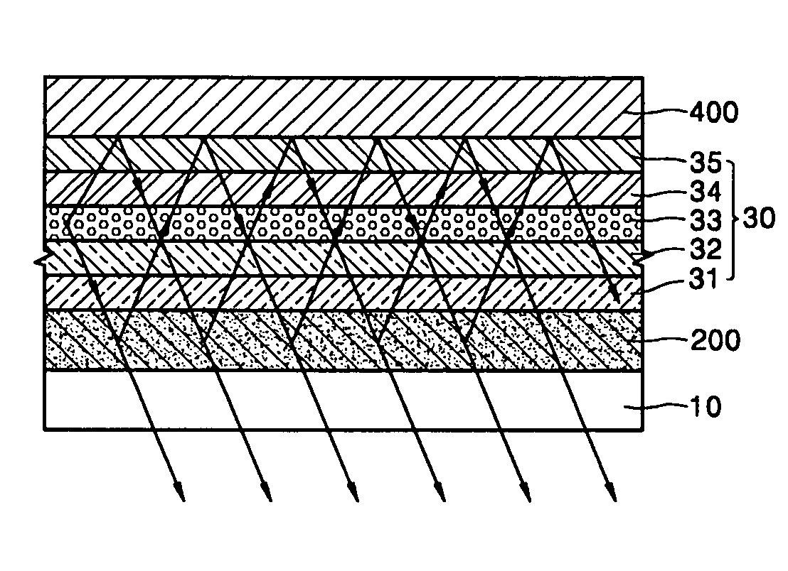
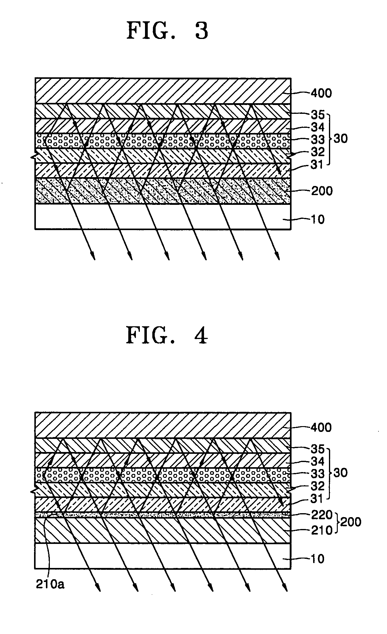
[0018]Hereinafter, an electroluminescent display according to a first exemplary embodiment of the invention will be described with reference to FIG. 3.
[0019]A bottom emission type electroluminescent display according to this exemplary embodiment comprises a transparent substrate 10, a first electrode 200, a second electrode 400, and a medium layer 30. The transparent substrate 10 may be a glass substrate, and the first electrode, the medium layer, and the second electrode are formed consecutively on the substrate. It should be understood that other layers may be included as well. One of the first electrode 200 and the second electrode 400 is an anode and the other electrode is a cathode. In all exemplary embodiments of the invention described herein including this embodiment, the first electrode is set as an anode and the second electrode is set as a cathode. However, the first electrode may be a cathode and the second electrode may be an anode.
[0020]The medium layer 30 is interpose...
PUM
 Abstract
Description
Claims
Application Information