Rule based proximity and time based tracking system

a technology of proximity and time based tracking, applied in the field of tracking and monitoring of objects, can solve the problems of not working well in many consumer applications, no information regarding objects for customers, and no communication path for voice or data message information, etc., and achieve the effect of convenient scheduling

Inactive Publication Date: 2007-03-06
BIFFAR PETER
View PDF14 Cites 122 Cited by
  • Summary
  • Abstract
  • Description
  • Claims
  • Application Information

AI Technical Summary

Problems solved by technology

One problem with this method of shipping is that the customer has no information regarding the object while it is in transit.
The most significant deficiency of the Loran system is that it provides no communication path for voice or data message information.
In many respects, the GPS system works as a “Loran-C-in-the-sky,” and performs well in open areas, but often does not work well in many consumer applications, and in urban areas.
Moreover, the cost of commercial GPS and Loran-C receivers is excessive and there is no means by which the location of a positioned object can be communicated beyond the object itself.
Unfortunately, the position of the vehicle between posts is unknown.
The capacity of the Teletrac system is limited to approximately 35 position fixes per second, and the system has little or no capacity to convey user information to the mobile location or back to the system.
These implementations, unfortunately, have been based on the current technology of voice-radio channels, which limit the capacity of the channel to practical data transmission rates in the range of 1,200 to 19,200 baud, with 2,400 to 4,800 baud being typical, depending on link budget and equipment cost.

Method used


Image

  • Rule based proximity and time based tracking system
  • Rule based proximity and time based tracking system
  • Rule based proximity and time based tracking system

Examples


Embodiment Construction

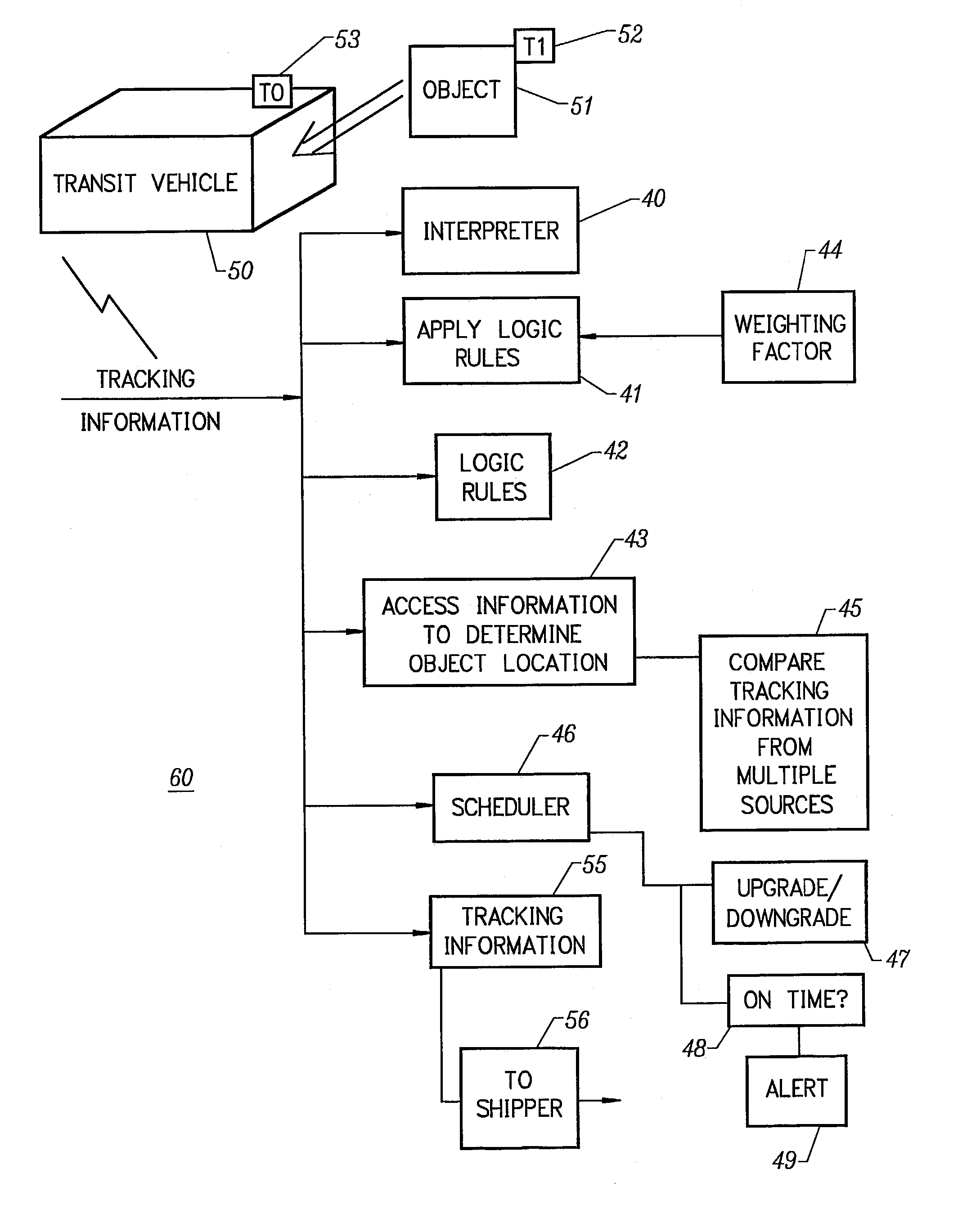
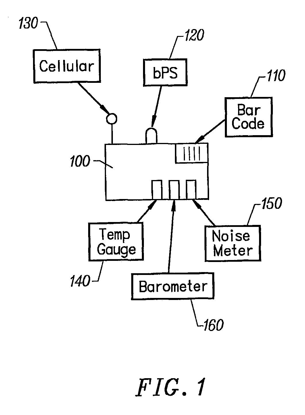
[0024]FIG. 1 illustrates the tracking tag 100 and the sources of information with which it is concerned. The tracking tag 100 is attached to an object, usually by an adhesive or other fixation means. The tracking tag preferably has a unique bar code 110 that is registered with the transportation system (TS). The TS consists of a tracking system and a scheduler (discussed infra). The TS keeps such information regarding the object as sender, address, item description, and any special handling instructions. The tracking tag may include such elements as a GPS signal receiver 120, a cellular phone type radio transmitter and receiver 130, a temperature gauge 140, a noise meter 150, and a barometer 160.

[0025]The tracking tag receives GPS satellite signals to determine its location by methods well known in the art. Similarly, the tracking tag determines and communicates its position using the radio signals traditionally used in cellular phones. The tag communicates its GPS position through ...


PUM


Abstract

A method and apparatus that automatically tracks, monitors and schedules the shipping of objects through carriers such as delivery trucks, ships, or planes is disclosed. A tracking tag is attached to each shipped object. The tracking tag and transportation system uses such techniques as GPS, cellular technology, and bar coding, and sensors such as those that make temperature, pressure, and noise measurements as sources of tracking information. Logic rules and hierarchical weights are given to each source, for any given condition so that the most accurate tracking is made. Tracking is continuous throughout the object's trip. Another set of logic rules is applied to take actions to intervene in the shipping process. For example if it seems the object is off schedule, upgrades or downgrades to the shipping are made. The transportation system can be integrated within a customer's company to facilitate easy scheduling, and production management. A user-friendly graphical user interface is available which displays item, time and distance related information.

Description

BACKGROUND OF THE INVENTION[0001]1. Technical Field[0002]The invention relates to the tracking and monitoring of an object. More particularly, the invention relates to an apparatus and to a family of methods that gather information on the location and transportation of an object, and that makes shipping decisions, independent of human input.[0003]2. Description of the Prior Art[0004]The tracking of shipping has increased over the years. As objects in transit move from place to place through, ships, planes, and trucks, carriers have sought to increase customer satisfaction by providing in-transit information. For example, Federal Express uses a bar code system in which a bar code is added to each shipped object. Each object is scanned at several points throughout its delivery trip. The scanned information is accessible to a customer through a customer service agent or through the Internet. One problem with this method of shipping is that the customer has no information regarding the ...

Claims


Application Information

Patent Timeline
Patent Type & Authority Patents(United States)
IPC IPC(8): G08B1/08G06Q10/08G07C9/00G08G1/123
CPCG06Q10/08G08G1/20G07C9/00111G07C2009/0092G07C9/28
Inventor BIFFAR, PETER
Owner BIFFAR PETER
Why Eureka
Try Eureka