Image forming method and charged particle beam apparatus

a technology of charged particle beam and image forming method, which is applied in the direction of pulse technique, television system, instruments, etc., can solve the problem of remaining inclined charging

Active Publication Date: 2007-03-06
HITACHI HIGH-TECH CORP
View PDF14 Cites 23 Cited by
  • Summary
  • Abstract
  • Description
  • Claims
  • Application Information

AI Technical Summary

Benefits of technology

[0009]According to such a configuration, the first, second and third scanning lines have intervals including a plurality of scanning lines. Therefore, it becomes possible to prevent residual charging on one scanning line from affecting other scanning lines. In addition, while scanning a plurality of scanning lines between the first and third scanning lines and between the second and third scanning lines, it is possible to mitigate the charging. Over the scanning area, therefore, it is possible to mitigate the influence of the absolute charging and suppress the inclination thereof.
[0011]According to such a configuration, the fourth scanning line is located in a position in the scanning area that is least susceptible to the influence of the charging on the first, second and third scanning lines. Therefore, it becomes possible to effectively suppress the inclination of the charging.
[0013]According to the present invention, it becomes possible to provide a method, and apparatus, for forming an image free from brightness inclination.

Problems solved by technology

Since the time interval for forming neighboring scanning lines is not sufficient, however, there is a problem that the inclination of charging remains.

Method used


Image

  • Image forming method and charged particle beam apparatus
  • Image forming method and charged particle beam apparatus
  • Image forming method and charged particle beam apparatus

Examples


first embodiment

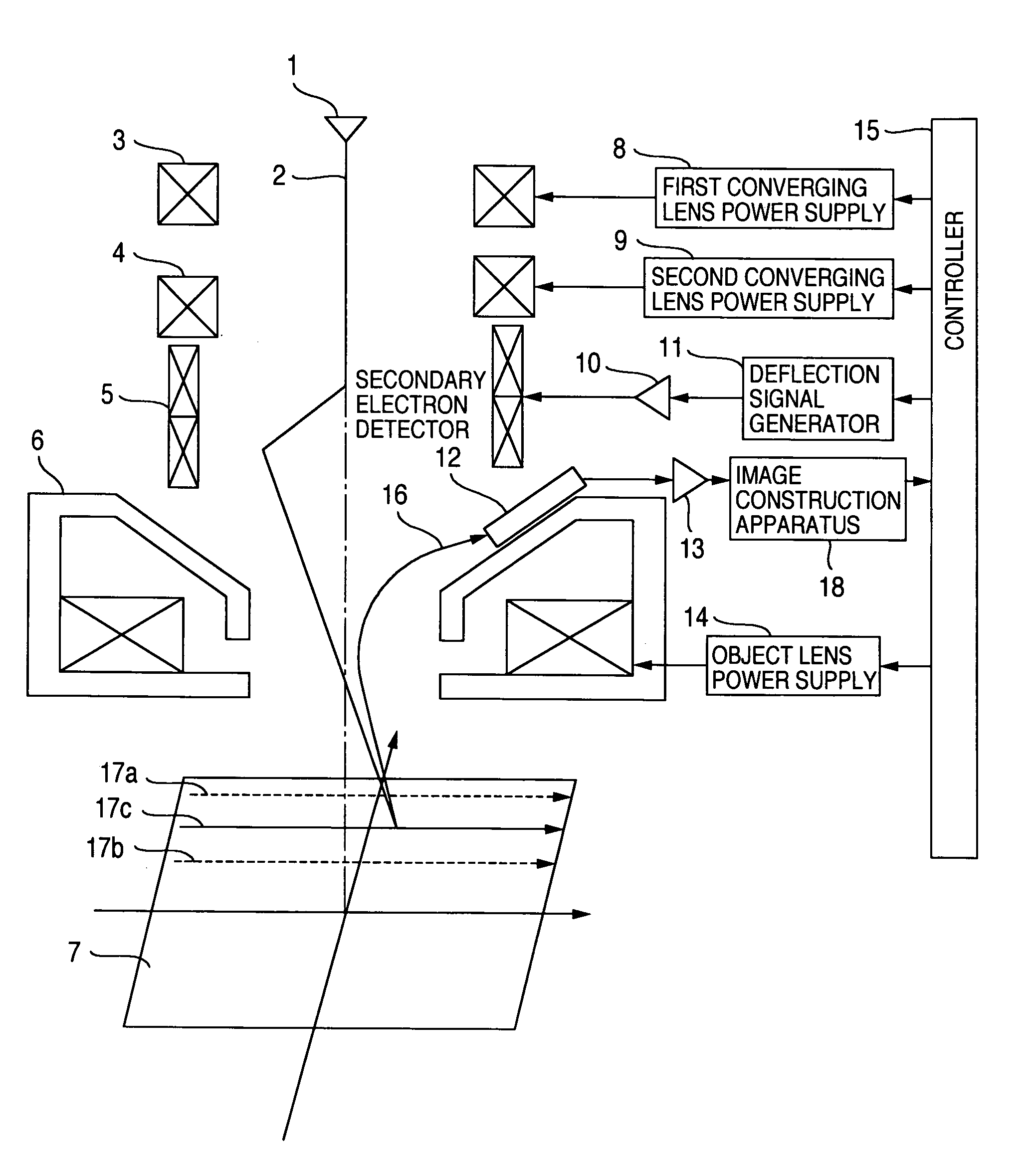
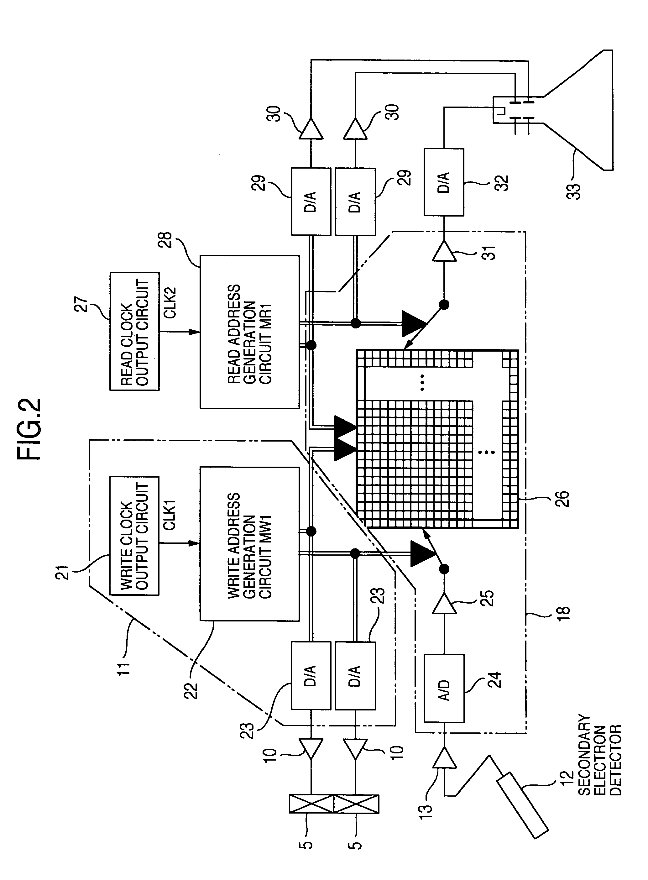
[0040]Hereafter, a first embodiment of the present invention will be described with reference to the drawings. A first embodiment of the present invention is shown in FIG. 1. The present embodiment will now be described by taking a scanning electron microscope which conducts scanning with an electron beam and forms a two-dimensional image of the sample as an example. However, the present embodiment is not restricted to this. If the influence of charging cannot be neglected, it is also possible to apply the present embodiment to an FIB (Focused Ion Beam) apparatus, which conducts scanning with an ion beam and forms an SIM (Scanning Ion Microscope) image.

[0041]As shown in FIG. 1, the present embodiment includes an electron beam source 1, a first converging lens 3 and a second converging lens 4 for focusing a primary electron beam 2 emitted from the electron beam source 1, deflectors 5 for deflecting the primary electron beam 2 to scan a surface of a sample 7 with the primary electron ...

second embodiment

[0069]An example in which pattern length measurement is conducted on the basis of an image formed using a scanning method of scanning a center line between scanning lines one after another as described above will now be described. FIG. 15 is a diagram showing an example of an image formed using the scanning method of the present example.

[0070]On this image, a line pattern bent in a part thereof by 90 degrees is displayed. When measuring the line width of such a line pattern, the scanning line direction of the raster scan and the sample direction are set in the conventional technique so as to make the pattern edge perpendicular to the scanning line direction of the raster scan. Because a length value measured in the scanning line direction of the raster scan becomes different from that measured in other directions as illustrated in FIG. 16 although the line width is the same. Since in this way the length value measured in the scanning line direction becomes different from that measur...

third embodiment

[0077]An example of further mitigating the influence of the charging by combining a faster scanning rate with the scanning method described with reference to the first embodiment will now be described. FIGS. 17A and 17B are diagrams showing deflection patterns (deflection patterns E and F represented by solid lines) used when scanning using the electron beam is conducted at a scanning rate that is twice with respect to the deflection patterns A and B described in the first embodiment. Observation and measurement become possible even for a sample affected by the charging more remarkably by combining the suppression of charging obtained using scanning faster than the ordinary scanning with the scanning method described with reference to the first embodiment.

[0078]FIG. 22 is a diagram showing an example of a GUI (Graphical User Interface) for setting various scanning methods including the scanning method of the present example and the scanning rate. In a GUI screen shown in FIG. 22, a ...


PUM


Abstract

An image forming method and a charged particle beam apparatus suitable for suppressing the inclination of charging when scanning a two-dimensional area with a charged particle beam. A third scanning line located between a first scanning line and a second scanning line is scanned. After the first, second and third scanning lines have been scanned, a plurality of scanning lines are scanned between the first and third scanning lines and between the second and third scanning lines.

Description

BACKGROUND OF THE INVENTION[0001]The present invention relates to an image forming method using a charged particle beam, and a charged particle beam apparatus. In particular, the present invention relates to an image forming method and a charged particle beam apparatus capable of suppressing the influence of charging.[0002]If an electron beam is applied to a sample, secondary electrons are generated. In scanning electron microscopes, an observed image on the surface of the sample is obtained using a phenomenon that the quantity of generation of secondary electrons changes depending upon the shape of the sample. In conventional scanning electron microscopes, scanning is conducted in the horizontal direction, i.e., in the raster direction in the screen every line (every horizontal line in the screen). The order of scanning lines is a descending order from the top to the bottom in the vertical direction in the screen.[0003]In the scan scheme according to the conventional technique, ras...

Claims


Application Information

Patent Timeline
Patent Type & Authority Patents(United States)
IPC IPC(8): G09G1/08G21K1/08H04N3/16
CPCH01J37/265H01J37/28H01J2237/31749H01J2237/1536
Inventor KOBARU, ATSUSHIMOROKUMA, HIDETOSHIKAWADA, HIROKITAKAMI, SHOSASADA, KATSUHIROYAMAMOTO, KOUICHISATOU, NORIONAKANISHI, KUNIO
Owner HITACHI HIGH-TECH CORP
Why Eureka
Try Eureka