Power unit for vehicle with internal combustion engine

a technology of power unit and internal combustion engine, which is applied in the direction of jet propulsion mounting, fluid coupling, gearing, etc., can solve the problems of reducing the mountability of the power unit on the vehicle body, and affecting the service life of the power unit. , to achieve the effect of reducing the capacity of the breather chamber, improving the vertical and horizontal directions of the power unit, and improving the mountability of the power unit on the vehicl

Inactive Publication Date: 2007-03-13
HONDA MOTOR CO LTD
View PDF7 Cites 13 Cited by
  • Summary
  • Abstract
  • Description
  • Claims
  • Application Information

AI Technical Summary

Benefits of technology

The technical effect of this patent is reducing the size of an electric motor used in vehicles with traditional engines, making it easier to install and maintain. Additionally, sensors measuring the movement of gears within the system have been placed near the sides of the vehicle for easy access during maintenance. A space between parts has also been created to prevent damage caused by oily drops generated during operation. Finally, directing the main axis of rotation towards the front or rear of the vehicle improves its overall performance and makes it simpler to inspect and fix any issues related to the speed change mechanism.

Problems solved by technology

The technical problem addressed in this patent is how to design a power unit for a vehicle without increasing its weight and space requirements, while also improving ease of installation and maintainance.

Method used


Image

  • Power unit for vehicle with internal combustion engine
  • Power unit for vehicle with internal combustion engine
  • Power unit for vehicle with internal combustion engine

Examples


Embodiment Construction

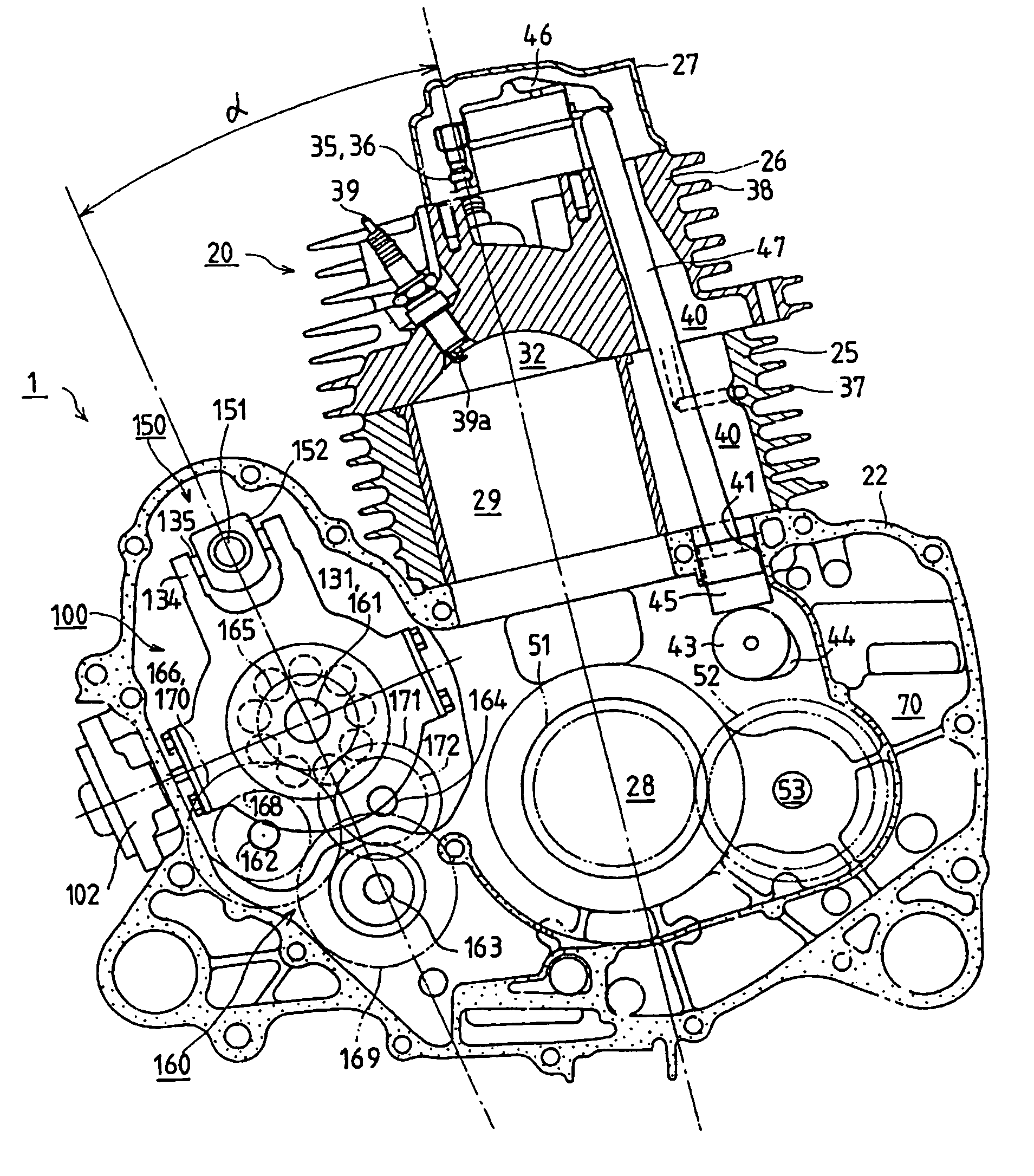
[0049]Now, an embodiment of a power unit for a vehicle with an internal combustion engine 1 according to the present invention shown in the drawings will be described. In this embodiment, the upward and downward directions mean the upward and downward directions with respect to the vehicle body, the front side means the front side with respect to the vehicle body, the rear side means the rear side with respect to the vehicle body, and the left and right mean the left and right as viewed from a person directed toward the front side.

Overall Structure

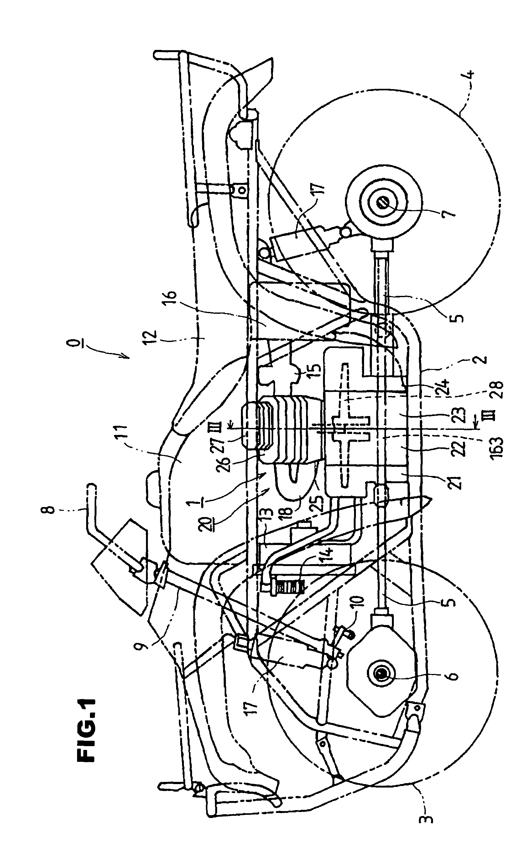
[0050]As shown in FIG. 1, in an off-road four-wheel vehicle 0 on which the power unit for vehicle with internal combustion engine 1 is mounted, pairs of front wheels 3 and rear wheels 4 are disposed respectively at front and rear portions of a vehicle body frame 2, the front end rear ends of transmission shafts directed in the forward and rearward directions from the power unit for vehicle with internal combustion engine 1 are connected to...


PUM


Abstract

A power unit for a vehicle with an internal combustion engine including a cylinder block and a crankshaft. A speed change drive shaft is disposed at a position on the upper side of a static oil hydraulic type non-stage transmission and in parallel to the axis of the transmission. A plane connecting the axis of the speed change drive shaft and the axis of the transmission does not intersect with the axis of the crankshaft, and intersects with the axis of the cylinder center axis of the cylinder block at a position on the lower side of the axis of the crankshaft while making an acute angle with the axis of the cylinder center axis of the cylinder block.

Description


Claims


Application Information

Patent Timeline
Owner HONDA MOTOR CO LTD
Why Eureka
Try Eureka