Solid oxide MEMS-based fuel cells

a fuel cell and solid oxide technology, applied in the field of fuel cells, can solve the problems of high cost, large system volume, and high cost of rechargeable and primary portable power sources with limited mission duration, and achieve the effects of reducing the cost of fuel cell production

Inactive Publication Date: 2007-03-13
LAWRENCE LIVERMORE NAT SECURITY LLC
View PDF13 Cites 67 Cited by
  • Summary
  • Abstract
  • Description
  • Claims
  • Application Information

AI Technical Summary

Benefits of technology

[0008]It is an object of the present invention to

Problems solved by technology

Present rechargeable and primary portable power sources have excessive weight, size, and cost with limited mission duration.
Typical fuel cells are made from bulk electrode-electrolyte materials which are stacked and manifolded using stainless

Method used


Image

  • Solid oxide MEMS-based fuel cells
  • Solid oxide MEMS-based fuel cells
  • Solid oxide MEMS-based fuel cells

Examples


Embodiment Construction

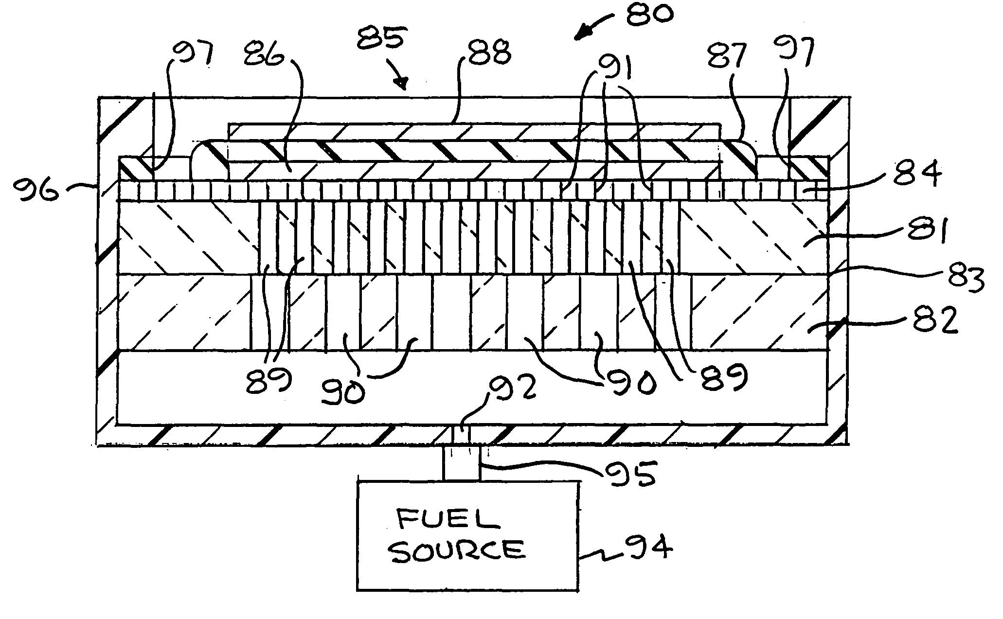
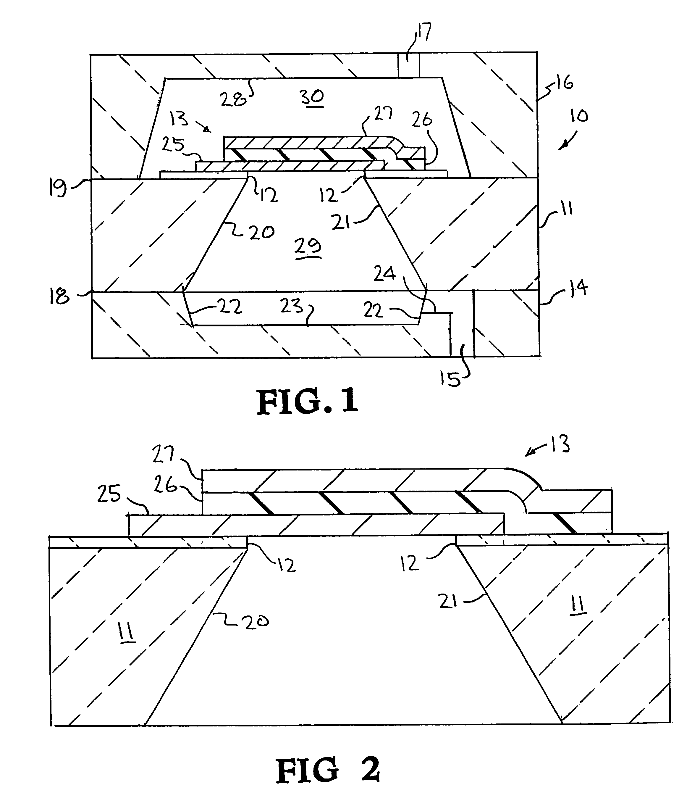
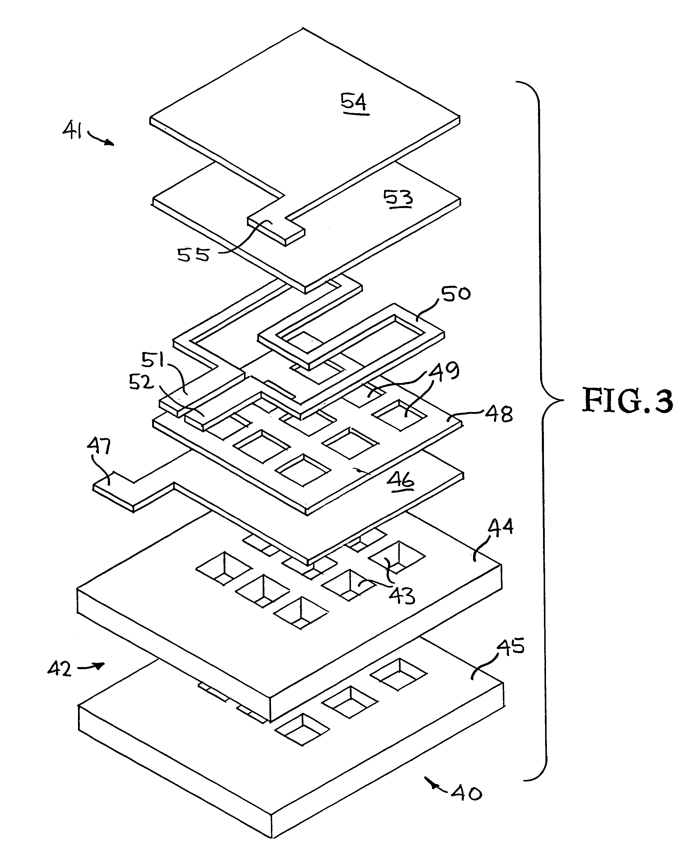
[0027]The present invention is a MEMS-based thin-film fuel cell or stack of fuel cells of either a solid oxide fuel cell (SOFC), a solid polymer fuel cell (SPFC), or a proton exchange membrane fuel cell (PEMFC), utilizing electrode / catalyst / electrolyte or electrode / electrolyte materials which enable the combination of a fuel and oxidant at elevated temperatures to produce continuous electric current. Fuel manifolds and microflow channels are formed in the host structure / substrate by MEMS-based technology and the electrode / electrolyte / electrode, with or without catalyst layers are formed along with resistive heaters and integrated control circuitry by thin-film deposition technology and microfabrication approaches in combination with MEMS fabrication techniques. Thus, the invention provides a miniature power source composed of fuel cells which yield zero emissions (when operated on hydrogen and air). The electrical current generated from each cell is drawn away with an interconnect a...


PUM

PropertyMeasurementUnit
Thicknessaaaaaaaaaa
Thicknessaaaaaaaaaa
Lengthaaaaaaaaaa

Abstract

A micro-electro-mechanical systems (MEMS) based thin-film fuel cells for electrical power applications. The MEMS-based fuel cell may be of a solid oxide type (SOFC), a solid polymer type (SPFC), or a proton exchange membrane type (PEMFC), and each fuel cell basically consists of an anode and a cathode separated by an electrolyte layer. The electrolyte layer can consist of either a solid oxide or solid polymer material, or proton exchange membrane electrolyte materials may be used. Additionally catalyst layers can also separate the electrodes (cathode and anode) from the electrolyte. Gas manifolds are utilized to transport the fuel and oxidant to each cell and provide a path for exhaust gases. The electrical current generated from each cell is drawn away with an interconnect and support structure integrated with the gas manifold. The fuel cells utilize integrated resistive heaters for efficient heating of the materials. By combining MEMS technology with thin-film deposition technology, thin-film fuel cells having microflow channels and full-integrated circuitry can be produced that will lower the operating temperature an will yield an order of magnitude greater power density than the currently known fuel cells.

Description

RELATED APPLICATION[0001]This application is a Continuation of application Ser. No. 09 / 241,159 filed Feb. 1, 1999 now U.S. Pat. No. 6,638,654 and claims priority thereto.[0002]The United States Government has rights in this invention pursuant to Contract No. W-7405-ENG-48 between the United States Department of Energy and the University of California for the operation of Lawrence Livermore National Laboratory.BACKGROUND OF THE INVENTION[0003]The present invention relates to fuel cells, particularly to small, compact fuel cells, and more particularly to a miniature power source composed of a stack of fuel cells fabricated by combining MEMS and thin film deposition technologies to produce fuel cells with microflow channels, fully-integrated control circuitry, and integrated resistive heaters.[0004]Portable power sources of various types have been under development for many years. A serious need exists for portable power sources with significantly higher power density, longer operating...

Claims


Application Information

Patent Timeline
IPC IPC(8): H01M8/04H01M8/12H01M8/24H01M8/10
CPCH01M8/1097H01M8/1286H01M8/241H01M8/2425H01M8/1213Y02E60/525H01M2008/1293H01M2300/0074H01M2300/0082Y02E60/521Y02E60/50H01M8/2485H01M8/2432
Inventor JANKOWKSI, ALAN F.MORSE, JEFFREY D.
Owner LAWRENCE LIVERMORE NAT SECURITY LLC
Why Eureka
Try Eureka