
Method for embedding information in an image

a technology for embedding information and images, applied in the field of printing images, can solve the problems of increasing the size of black areas, unable to align scanned pixels perfectly with printed pixels, etc., and achieve the effect of reducing the production of fraudulent images and difficult to copy images

Inactive Publication Date: 2007-03-13
PITNEY BOWES INC
View PDF18 Cites 37 Cited by
  • Summary
  • Abstract
  • Description
  • Claims
  • Application Information

AI Technical Summary

Benefits of technology

[0005]This invention overcomes the disadvantages of the prior art by providing a method that makes it more difficult to copy images. The invention provides a method that detects when an image is copied or scanned to reduce the production of fraudulent images. Information in the form of a plurality of numbers and / or characters (in a normal or encrypted form) that represents some fact, i.e., date that an indicia was affixed to a mail piece, zip code, etc., is going to be embedded in an image in a manner that the embedded information will change in appearance when the image is scanned or photocopied.
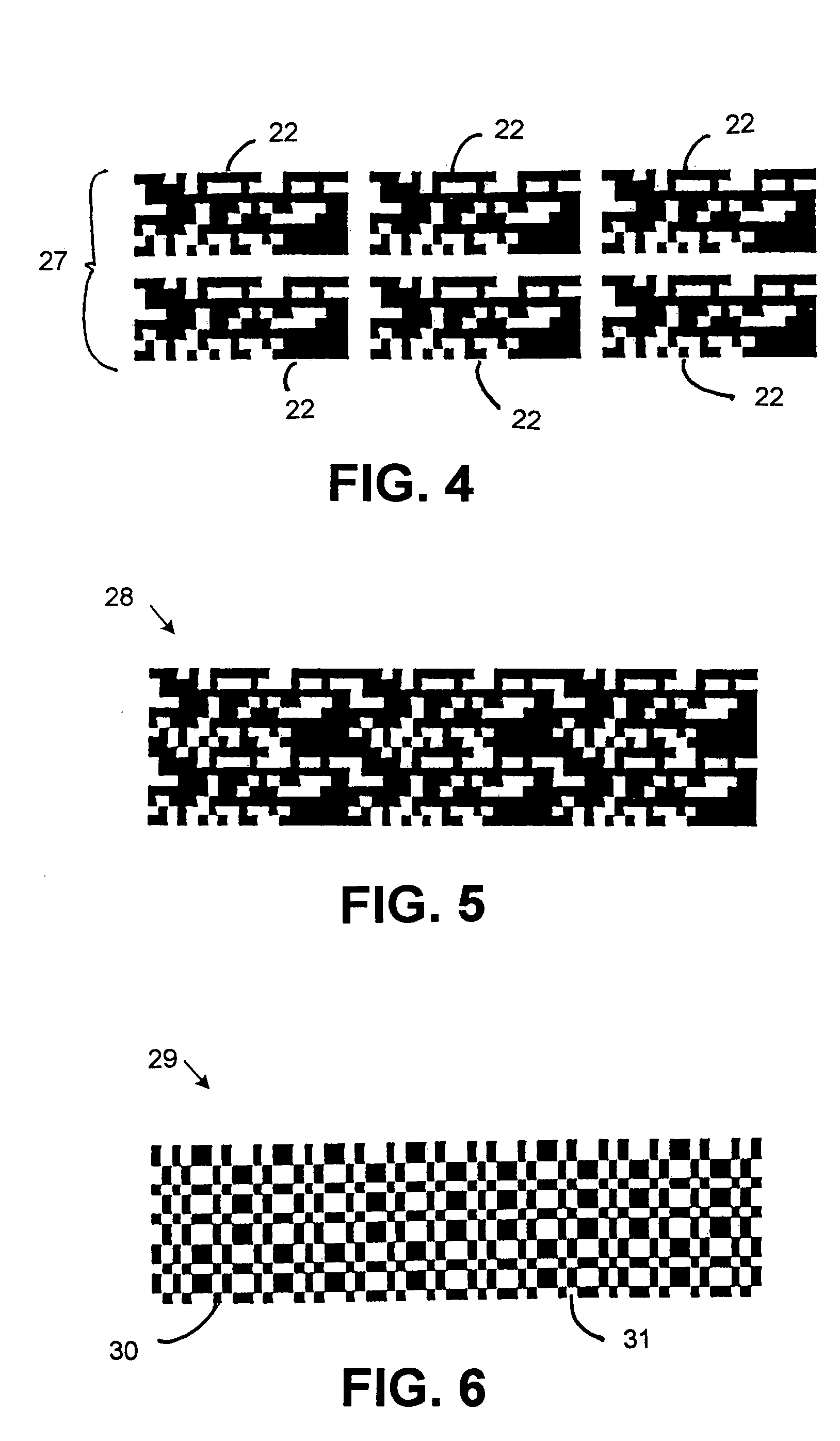
[0006]The foregoing is accomplished by converting the plurality of numbers into a two-dimensional bar code that is repeated m times in the horizontal direction and n times in the vertical direction in order to produce redundancy so that the two-dimensional bar code will be easier to recover. The two-dimensional bar codes are then filtered by a spreading algorithm that scrambles the information represented by the two-dimensional bar code. Each scrambled two-dimensional bar code will be the same size as the two-dimensional bar code that it replaces. Then each scrambled two-dimensional bar code will be split into two equal parts, i.e., a first part and a second part. Each first part and each second part will contain an upper portion and a lower portion. The upper portion of the first part and the lower portion of the second part will be the same as the respective upper and lower parts of the scrambled two-dimensional bar code. The lower portion of the first part and the upper portion of the second part will be white or empty space. Spread spectrum-like techniques will then be applied to the first part and second part to further hide the information in the first and second parts and to make it easier to recover the information in the first and second parts. Then the plurality of first and second parts will be expanded over the entire image that is going to be printed. At each location in which information from the plurality of first parts is going to be printed, the printed information will be a printed pixel of a specified dimension, i.e., 2×2 pixels. At each location in which information from the plurality of second parts is going to be printed, the printed information will be a printed pixel of a specified dimension that differs from the pixels printed in the first parts, i.e., 3×3 pixels. The pixels of the first part and the pixels of the second part do not overlap. The plurality of first and second parts will then be printed over the image to produce an image containing hidden information that is difficult to copy. When the image and plurality of first and second parts are scanned and printed and / or photocopied, the printed pixels of specified dimensions in the first and second parts will be distorted in the bit map. In addition, the scanned pixels will not align perfectly with the printed pixels. When the scanned image is converted back to a bit map, this usually increases the percentage of black pixels. Thus, the combination of optical effects, digitations effects and ink spread increase the size of the black areas. The change in size of the printed pixels of specified dimensions in the first and second parts may be observable by the human eye and / or a scanner. Thus, one will be able to determine when an image is copied.

Problems solved by technology

In addition, the scanned pixels will not align perfectly with the printed pixels.
Thus, the combination of optical effects, digitations effects and ink spread increase the size of the black areas.

Method used


Image

  • Method for embedding information in an image
  • Method for embedding information in an image
  • Method for embedding information in an image

Examples


Embodiment Construction

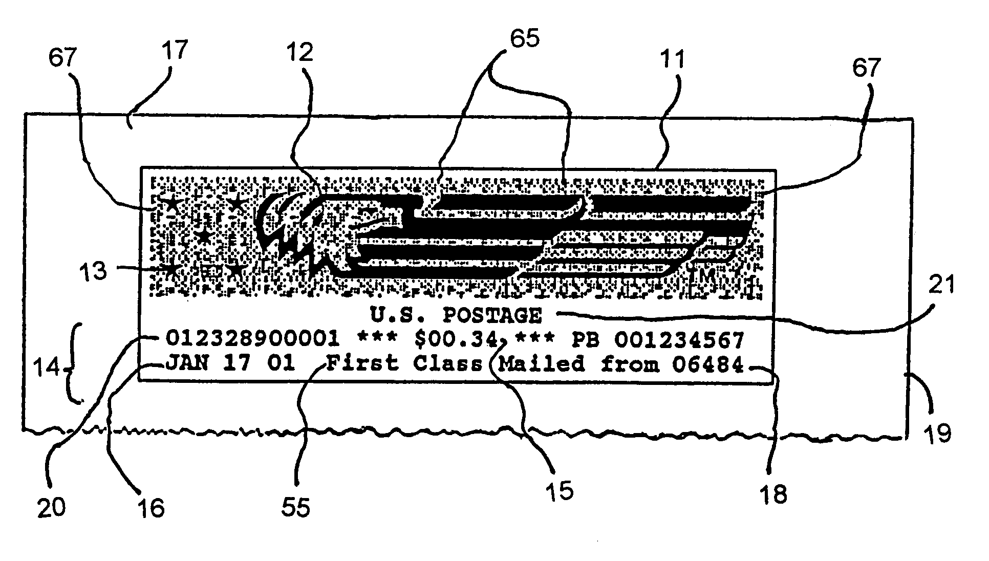
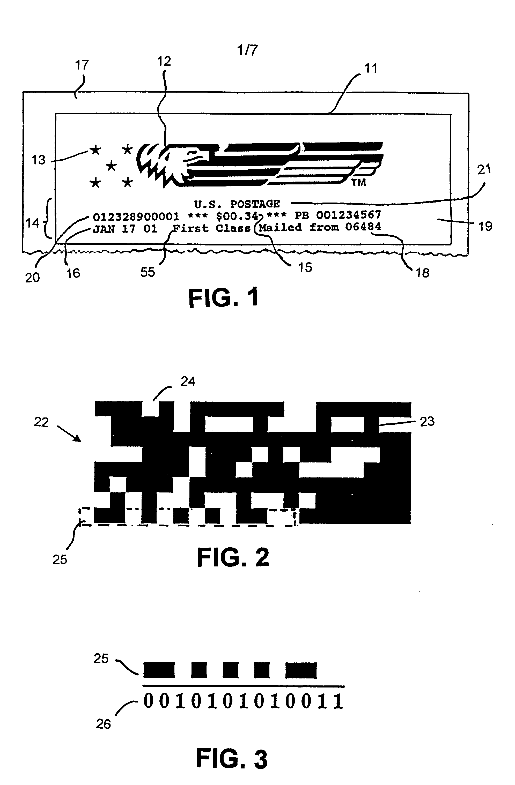
[0024]Referring now to the drawings in detail, and more particularly to FIG. 1, the reference character 11 represents a postal indicia. Postal indicia 11 includes graphic material in the form of an eagle 12 and stars 13 and alphanumeric material 14. Indicia 11 also contains a dollar amount 15; the date 16 that postal indicia 11 was affixed to mail piece 17; the zip code where mail piece 17 was mailed from 18; the postal meter serial number 19; a security code 20; the class of mail 55; and the country 21.

[0025]FIG. 2 is a drawing of a two-dimensional bar code 22 that represents in coded form the information contained in material 14 and other information. Bar code 22 comprises a plurality of black modules 23 and white modules 24. Black modules 23 represent a “zero”, and white modules 24 represent a “one”. Portion 25 of bar code 22 represents the zip code 18 of FIG. 1 with the least significant bit on the left.

[0026]FIG. 3 is a drawing of portion 25 of bar code 22. The binary represent...


PUM


Abstract

A method for producing a background image representing data. The background image is created by; producing a first encoding of data into a first binary array; producing a second encoding of the data into a second binary array; representing the first binary array as a first set of modules of a first size of n×n pixels wherein each pixel is either white or black and every pixel in the module is identical to every other picture in the module on nodes of a first lattice, representing the second binary array as a first set of modules of a second size, of m×m wherein each pixel is either white or black and every pixel in the module is identical to every other pixel in the module, which is smaller than the first size on nodes of a second lattice, combining the first and second sets of modules; and printing the first and second sets of modules.

Description

CROSS REFERENCE TO RELATED APPLICATIONS[0001]Reference is made to commonly assigned copending patent application Ser. No. 10 / 087,492 filed herewith entitled “Method For Reading Information That Has Been Embedded In An Image” in the names of Robert A. Cordery, Claude Zeller, Donald G. Mackay and William A. Brosseau; and Ser. No. 10 / 087,314 filed herewith entitled “Method For Utilizing A Fragile Watermark For Enhanced Security” in the names of Claude Zeller, Donald G. Mackay, William Kilmartin, William A. Brosseau, James Euchner and Robert A. Cordery (Ser. No. 10 / 087,314 claims the benefit of the filing date of U.S. Provisional Application No. 60 / 283,565 filed Apr. 13, 2001, which is owned by the assignee of the present Application).FIELD OF THE INVENTION[0002]The subject invention relates to a method for printing images that contain certain information and, more particularly, to a method that detects when the printed images containing certain information are copied.BACKGROUND OF THE ...

Claims


Application Information

Patent Timeline
IPC IPC(8): H04L9/00H04L9/28G06K19/06G07B17/00H04N1/00
CPCG07B17/00733H04N1/00883H04N1/00838G07B2017/00822
Inventor ZELLER, CLAUDECORDERY, ROBERT A.MACKAY, DONALD G.BROSSEAU, WILLIAM A.
Owner PITNEY BOWES INC
Learn More