Servo driven quilter

a servo-driven, quilting technology, applied in the direction of combination sewing machines, sewing machine control devices, textiles and paper, etc., can solve the problems of needle deflection, needle deflection, and increased likelihood of stitches being missed, and achieve high ornamental quality and quilting at high speed

Inactive Publication Date: 2007-03-20
L & P PROPERTY MANAGEMENT CO
View PDF1 Cites 19 Cited by
  • Summary
  • Abstract
  • Description
  • Claims
  • Application Information

AI Technical Summary

Benefits of technology

[0009]An objective of the present invention is to provide a computer controlled pattern quilting method and apparatus that will provide wide variety of quilted patterns, particularly patterns of a high ornamental quality. A particular objective of the present invention is to provide a quilting method and apparatus employing a single needle quilting head and having the capability of quilting at high speed, particularly on thick materials such as those used for mattress covers.

Problems solved by technology

Needle deflection is more of a problem when quilting thick materials and complex patterns that involve many directional changes in the sewing path, particularly where higher sewing speeds are used.
A drawback to the use of double-lock chain-stitch machines has been the greater likelihood for stitches to be missed as a result of needle deflection.
Misalignment of the needle and looper due to deflection of the needle can result in the missing of stitches which, in the formation of more highly decorative patterns, is undesirable for not only aesthetic reasons but because it can result in an unraveling of the stitched pattern.
Attempts at high speed sewing on mattress covers, where the material is generally very thick and the outer or ticking layer of fabric may be heavy and even of an upholstery-like nature, produce unavoidable needle deflection.
To this end, equipment of the prior art such as discussed above has had limitations.

Method used


Image

  • Servo driven quilter
  • Servo driven quilter
  • Servo driven quilter

Examples


Embodiment Construction

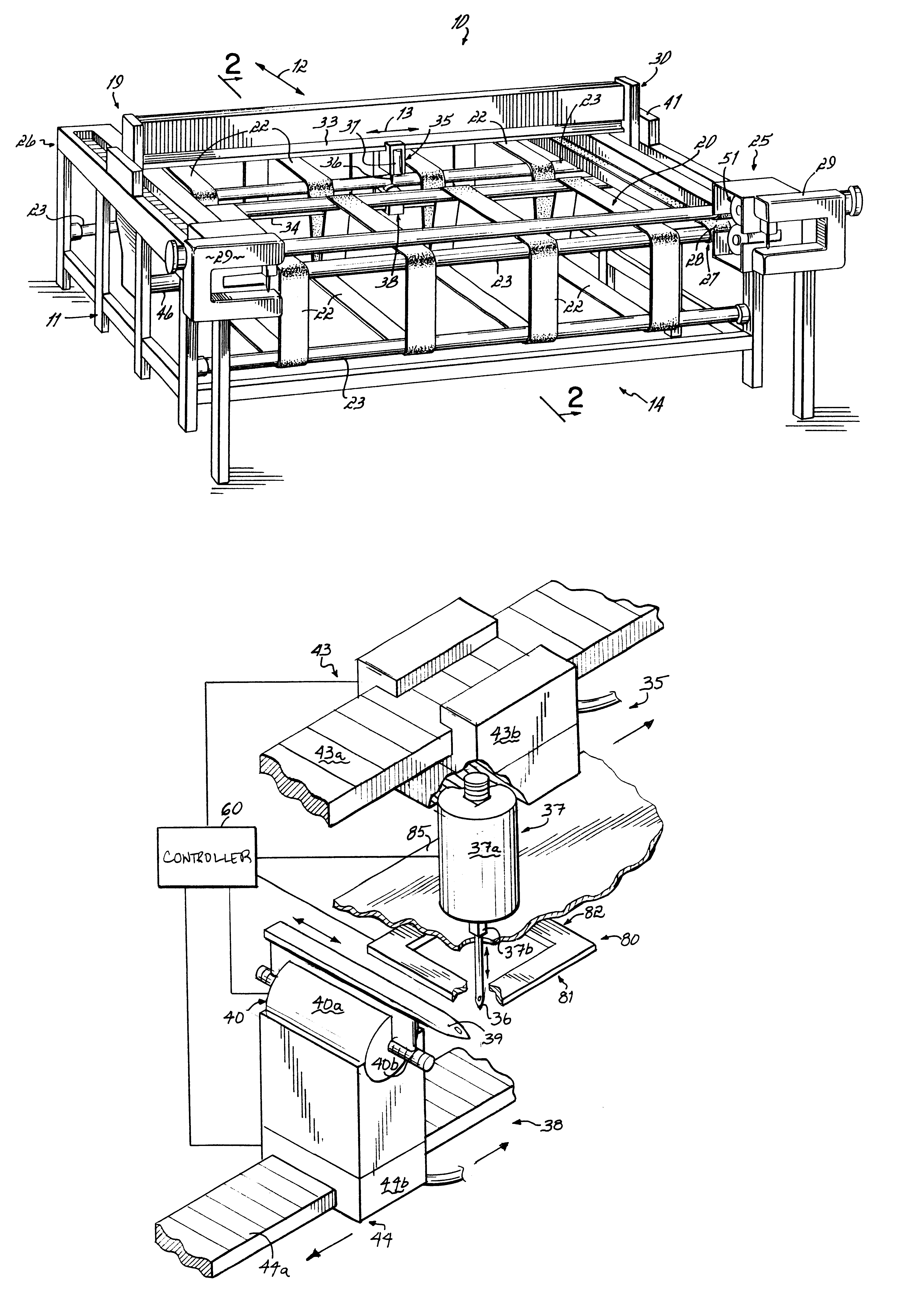
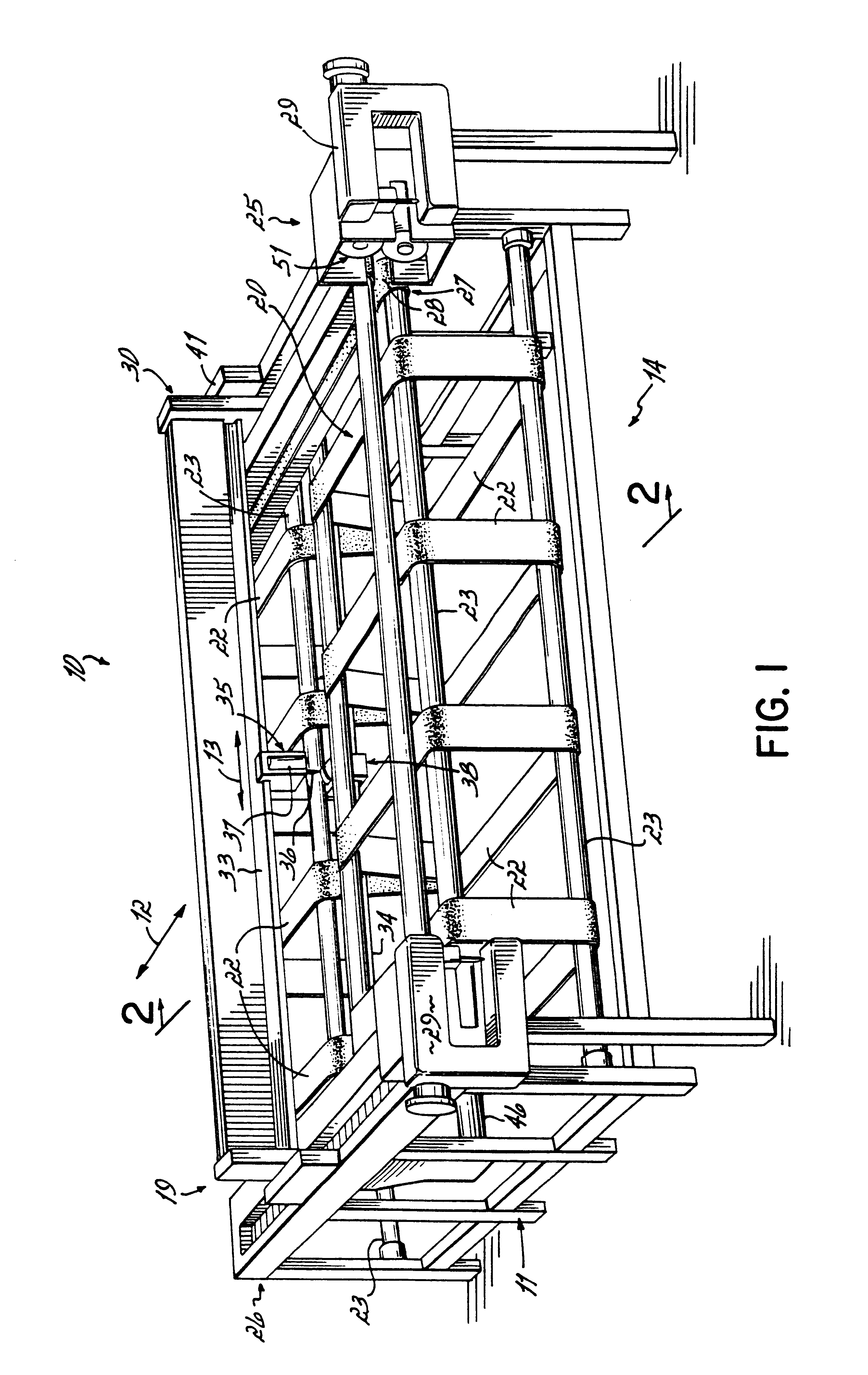
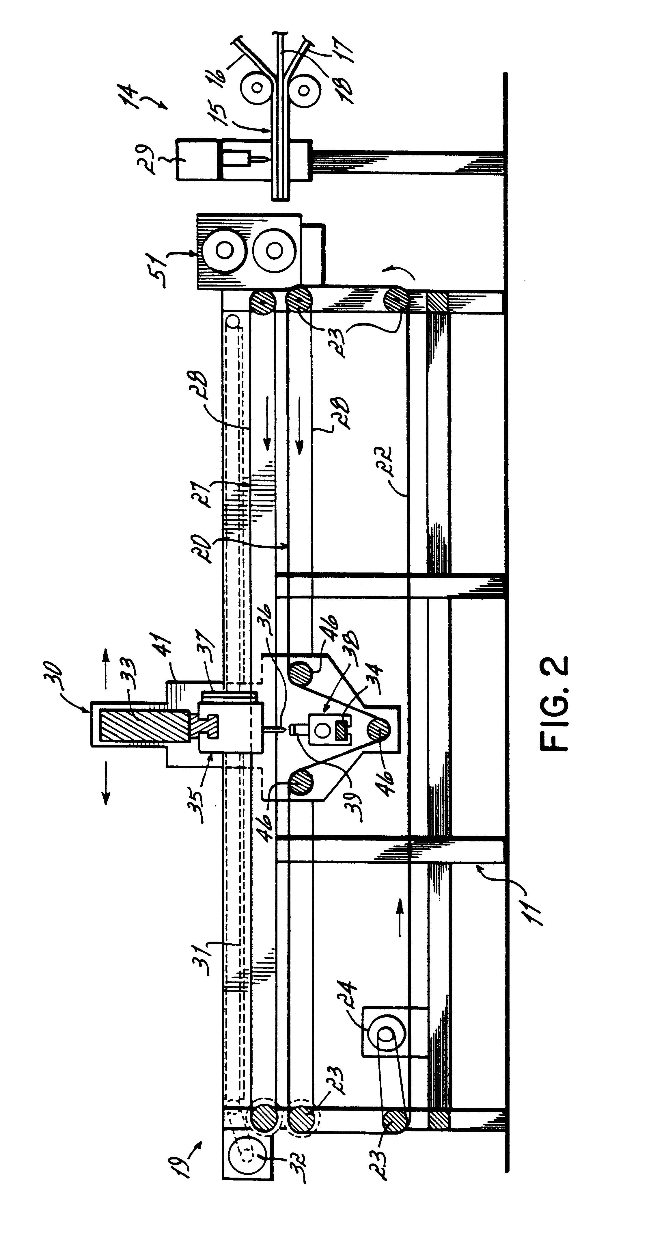
[0035]FIGS. 1 and 2 illustrate a quilting machine 10 having a stationary frame 11 with a longitudinal extent represented by arrow 12 and a transverse extent represented by arrow 13. The machine 10 has a front end 14 into which is advanced a web 15 of multi-layered material that includes a facing material layer 16, a backing material layer 17 and a filler layer 18. The machine 10 also has a back end 19 from which quilted multilayered material is advanced to a take-up or panel cutting section (not shown).

[0036]On the frame 11 is mounted a conveyor table 20 that includes a set of longitudinally extending belts 22 supported on a set of transverse rollers 23 journaled to the frame 11 to rotate thereon under the power of a drive motor 24. The motor 24 drives the belts 22 to advance the unquilted web 15 onto the frame 11 at the front end 14 thereof and to advance a quilted portion of the web 15 from the frame 11 to the take-up section at the back end 19 of the machine 10. The belts 22 supp...


PUM


Abstract

A quilting machine has at least one needle and looper set for forming chain-stitched patterns on a thick multilayered material such as a mattress ticking, preferably a panel of the continuous web clamped stationary on a frame. The stitch forming elements are mounted on separate heads that move independently transversely relative to the panel on a bridge that moves longitudinally relative to the panel. The bridge is longitudinally moved by a servo and the heads are transversely moved on the bridge by separate linear servos. The needle and looper are each driven by a linear servo having an armature to which the element is directly fixed to reciprocate without intervening mechanical linkage assemblies. A controller drives the servos to chain-stitch patterns, differentially move the heads transversely to account for transverse needle deflection and to phase the needle and looper to compensate for longitudinal needle deflection. The controller determines or predicts needle deflection, either based on stored empirically determined data or optical sensing, and generates deflection compensation signals to drive the servos.

Description

[0001]This is a continuation-in-part of the copending and commonly assigned U.S. application Ser. No. 09 / 189,656, filed Nov. 10, 1998, now U.S. Pat. No. 6,178,903 which is a continuation in part of commonly assigned and copending U.S. application Ser. No. 08 / 831,060, filed Apr. 11, 1997, now U.S. Pat. No. 5,832,849, both hereby expressly incorporated by reference herein.FIELD OF THE INVENTION[0002]The present invention relates to the quilting of patterns on multiple layer materials, and particularly to the stitching of patterns on thick multilayer materials such as mattress covers.BACKGROUND OF THE INVENTION[0003]Quilting is a special art in the general field of sewing in which patterns are stitched through a plurality of layers of material over a two dimensional area of the material. The multiple layers of material normally include at least three layers, one a woven primary or facing sheet having a decorative finished quality, one a usually woven backing sheet that may or may not b...

Claims


Application Information

Patent Timeline
Patent Type & Authority Patents(United States)
IPC IPC(8): D05B11/00D05B19/14D05B69/24
CPCD05B11/00D05B69/24D05B19/14
Inventor MYERS, TERRANCE L.BONDANZA, JAMESBULNES, ROLANDKAETTERHENRY, JEFFFRAZER, JAMES T.LEAVIS, GLENN E.
Owner L & P PROPERTY MANAGEMENT CO
Why Eureka
Try Eureka