Internal combustion engine

a technology of internal combustion engine and combustion chamber, which is applied in the direction of machines/engines, mechanical equipment, lighting and heating apparatus, etc., to achieve the effect of reducing the dimensions of radiators, reducing the heat of internal combustion engines, and eliminating them

Inactive Publication Date: 2007-03-20
HONDA MOTOR CO LTD
View PDF15 Cites 73 Cited by
  • Summary
  • Abstract
  • Description
  • Claims
  • Application Information

AI Technical Summary

Benefits of technology

[0006]In accordance with this arrangement, since the cooling water passage is formed in multiple layers so as to cover the combustion chamber, it is possible to ensure that the overall length of the cooling water passage is sufficiently long, thereby cooling effectively the cylinder head around the combustion chamber. Moreover, since the cooling water flows from a layer on the side far from the combustion chamber toward a layer on the side close to the combustion chamber, that is, the cooling water flows in a direction opposite to the direction of emission of the heat of combustion from the combustion chamber, it is possible to ensure that there is sufficient difference in temperature between the cylinder head and the cooling water throughout the cooling water passage, thereby further improving the effect of the cooling water in cooling the cylinder head. In this way, the surroundings of the combustion chamber of the internal combustion engine, where the temperature is the highest, can be cooled effectively, thus increasing the temperature of the cooling water and thereby improving the efficiency of recovery of waste heat.
[0008]In accordance with this arrangement, since the cooling water that has passed through the cooling water passage and whose temperature has thereby been increased is used as the heat source for other auxiliary equipment, waste heat of the internal combustion engine can be utilized effectively without being wastefully disposed of and, furthermore, it is possible to reduce the dimensions of a radiator or eliminate it because of the decrease in temperature of the cooling water.

Problems solved by technology

In order to recover as much as possible of the waste heat of an internal combustion engine as high temperature steam, it is not sufficient just to make an evaporator provided in an exhaust passage exhibit its full performance by maintaining the exhaust gas at a high temperature; it is also necessary to recover heat that is transferred from the combustion chamber to the cylinder head and dissipated into the air.

Method used


Image

  • Internal combustion engine
  • Internal combustion engine
  • Internal combustion engine

Examples


Embodiment Construction

[0016]An embodiment of the present invention is explained below with reference to FIG. 1 to FIG. 6.

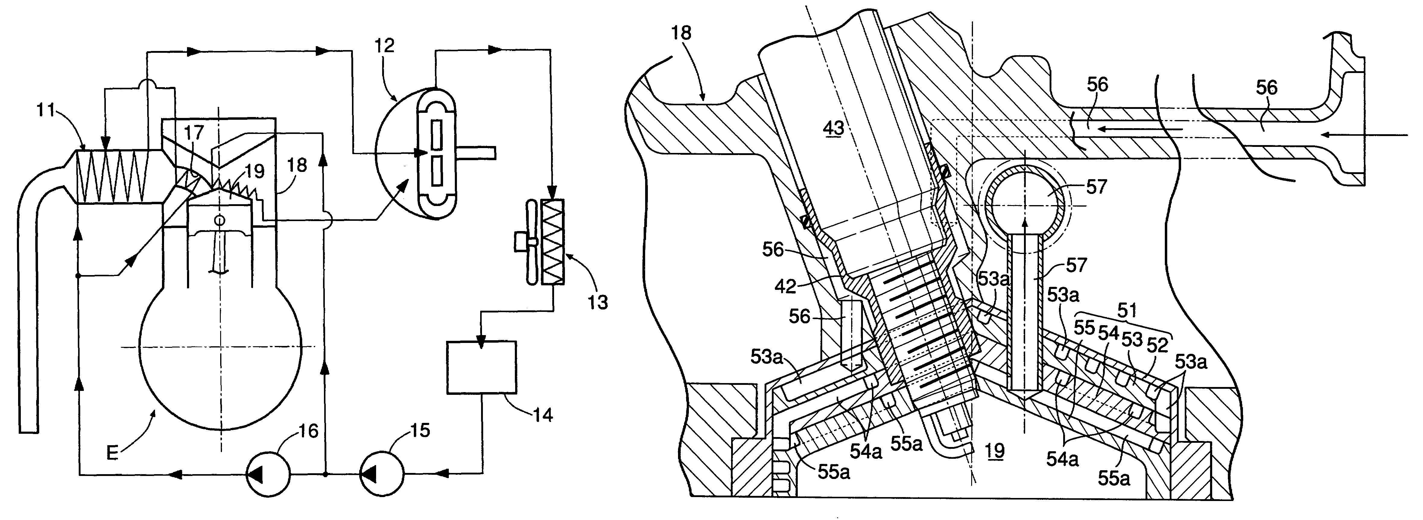
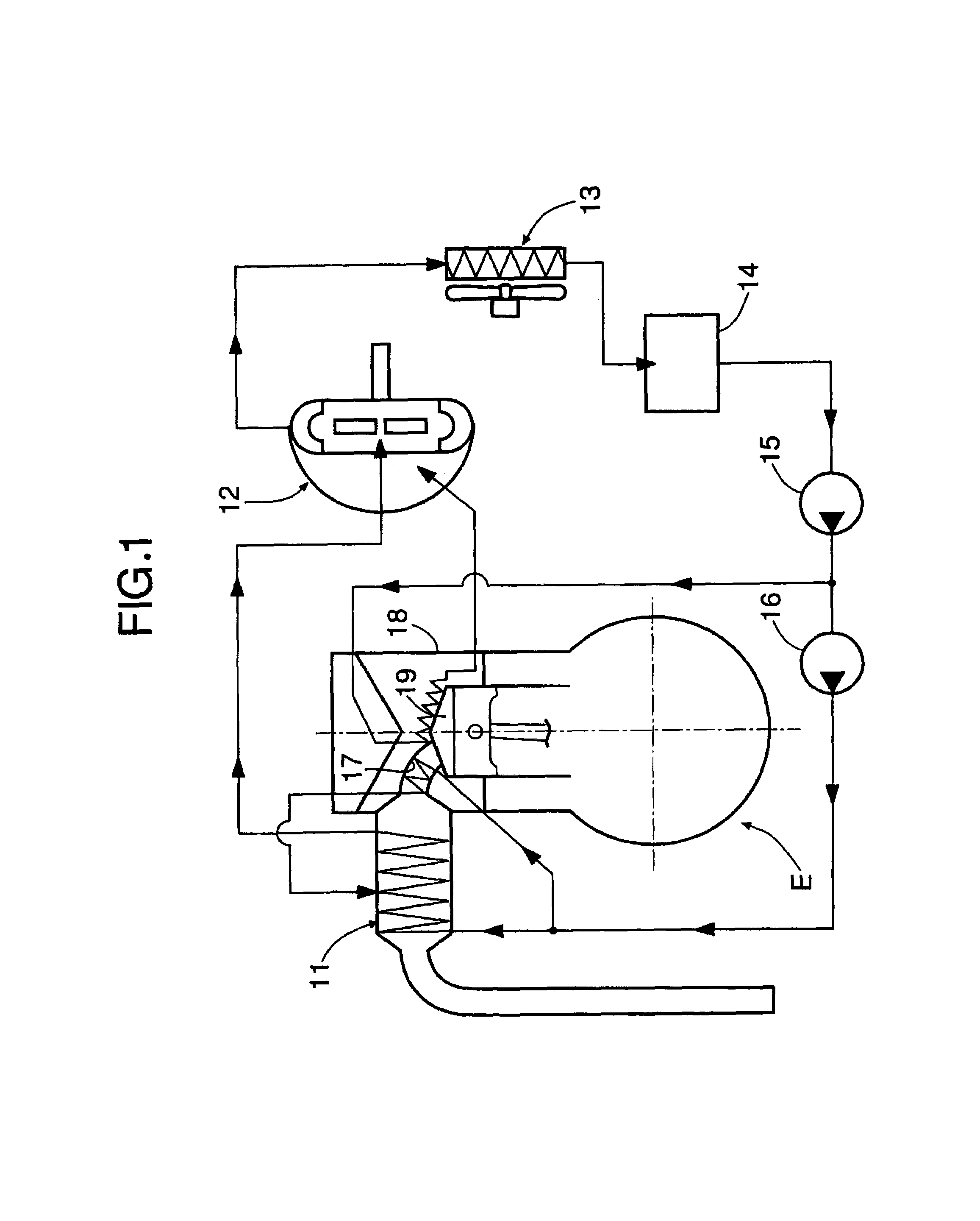
[0017]FIG. 1 shows the overall arrangement of a Rankine cycle system to which the present invention is applied.

[0018]The Rankine cycle system, which recovers the thermal energy of exhaust gas of an internal combustion engine E and converts it into mechanical energy, includes a first evaporator 11 that heats water using the exhaust gas discharged from the internal combustion engine E so as to generate high temperature, high-pressure steam, an expander 12 that is operated by the high temperature, high-pressure steam generated by the first evaporator 11 so as to generate mechanical energy, a condenser 13 that cools decreased temperature, decreased pressure steam that has completed work in the expander 12 so as to turn it back into water, a reservoir tank 14 for collecting water discharged from the condenser 13, a low-pressure pump 15 for pressurizing the water collected in the reservoir t...


PUM


Abstract

A cooling block forming a top wall of a combustion chamber of an internal combustion engine is formed by layering, from the outside to the inside, a casing, an upper layer block, a middle layer block, and a lower layer block. Labyrinth-shaped cooling water passages are formed on upper side faces of the three layers of blocks, and cooling water supplied from a cooling water supply passage flows from the cooling water passage on the side far from the combustion chamber to the cooling water passage on the side close to the combustion chamber, and is discharged from a cooling water discharge passage. Since the cooling water flows in a direction opposite to the direction of emission of heat of combustion from the combustion chamber, it is possible to ensure that there is sufficient difference in temperature between a cylinder head and the cooling water throughout the cooling water passages.

Description

FIELD OF THE INVENTION[0001]The present invention relates to an internal combustion engine that includes, within a cylinder head, a cooling water passage above a combustion chamber, the cooling water passage cooling the heat of combustion that is transferred from the combustion chamber to the cylinder head.BACKGROUND ART[0002]There is known from Japanese Patent Application Laid-open No. 2001-207908 an arrangement in which a cooling water passage is formed in a cylinder head of an internal combustion engine so as to cover an upper part of a combustion chamber. A large amount of cooling water is made to flow through a section of the cooling water passage where there is a large thermal load and a small amount of cooling water is made to flow in a section where there is a small thermal load so that the cylinder head is cooled to the minimum necessary; as a result, the temperature of exhaust gas is maintained as high as possible, thereby promoting warm-up of the internal combustion engin...

Claims


Application Information

Patent Timeline
Patent Type & Authority Patents(United States)
IPC IPC(8): F02F1/36F01P3/02F01P3/20F02F1/26F02F1/40F28F13/00F02F1/38F02G5/02
CPCF01P3/02F02F1/40F02G5/02F02F1/38F01P2003/024Y02T10/166Y02T10/12
Inventor BABA, ATSUSHIENDOH, TSUNEOSHINOHARA, MASASHI
Owner HONDA MOTOR CO LTD
Why Eureka
Try Eureka