
Tunable, maximum power output, frequency harmonic comb generator

a frequency harmonic comb and generator technology, applied in pulse generators, pulse manipulation, pulse techniques, etc., can solve the problem of fixed pulse width in output signals

Inactive Publication Date: 2007-03-20
NORTHROP GRUMMAN SYST CORP
View PDF10 Cites 14 Cited by
  • Summary
  • Abstract
  • Description
  • Claims
  • Application Information

AI Technical Summary

Benefits of technology

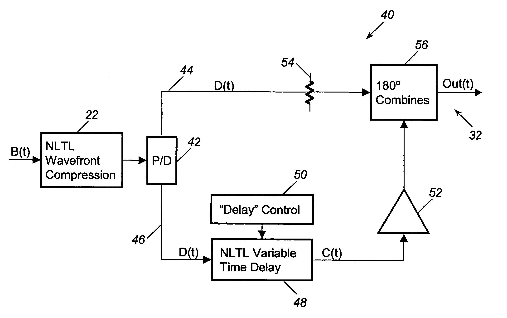
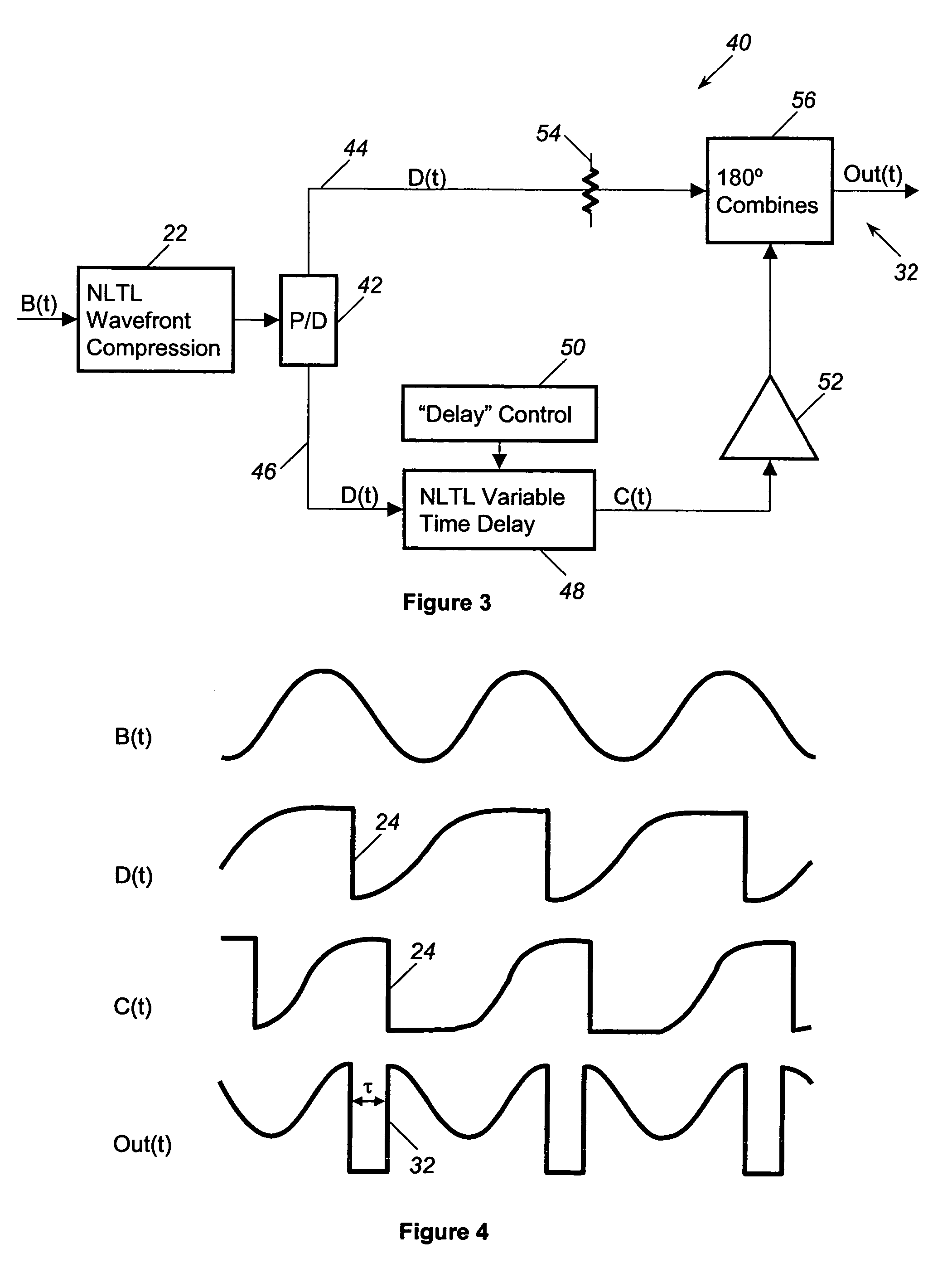
The present invention is about a device that can generate a maximum output power for different harmonic frequencies of an input signal. It uses a wavefront compression device, such as a non-linear transmission line (NLTL) with step recovery diodes, to create an output signal with periodic fast edges. The fast edge signal is then applied to a shorted transmission line stub with switching devices to control the delay of the signal. This results in a pulsed signal with controlled width. In an alternate embodiment, the fast edge signal is sent to a power divider and then combined with another fast edge signal that has been delayed using a time delay device. This results in a pulsed signal with controlled width and edges that do not align. The invention has advantages in generating high-resolution pulsed signals.

Problems solved by technology

A disadvantage exists with the known comb generators because the width of the pulses in the output signal is fixed and is not variable.
This disadvantage is a significant problem for those applications where different harmonics may be selected at different times during operation of the generator or for multi-channel devices.

Method used


Image

  • Tunable, maximum power output, frequency harmonic comb generator
  • Tunable, maximum power output, frequency harmonic comb generator
  • Tunable, maximum power output, frequency harmonic comb generator

Examples


Embodiment Construction

[0018]The following discussion of the embodiments of the invention directed to a tunable comb frequency generator is merely exemplary in nature, and is in no way intended to limit the invention or its applications or uses.

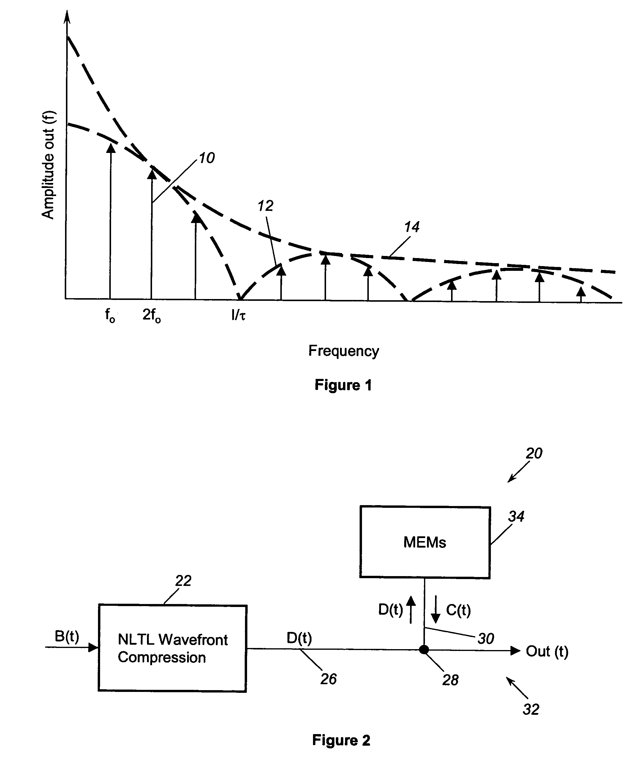
[0019]FIG. 2 is a schematic block diagram of a tunable comb frequency generator 20, according to one embodiment of the present invention. A sinusoidal, or near sinusoidal, input signal B(t), shown in FIG. 4, is applied to an NLTL device 22 that provides wavefront compression. In this embodiment, the NLTL device 12 is a transmission line that incorporates periodic Schottky varactor diodes to provide the wavefront compression and the fast edge signals. However, any suitable wavefront compression device can be used consistent with the discussion herein. In this embodiment, the input signal B(t) is a relatively large signal that self-biases the diodes in the NLTL device 22, causing a reduction in propagation time when the reverse bias of the diodes is greater. This cau...


PUM


Abstract

A comb frequency generator that is tunable to vary the width of the pulses in the output signal and achieve a maximum power output at different harmonic frequencies. A wavefront compression device receives a sinusoidal input signal and provides wavefront compression to create a compressed signal having a series of periodic fast edges. A delay device receives the fast-edge compressed signal and delays the fast-edge signal to create a delayed fast-edge signal. A combining device receives the original fast-edge compressed signal and the delayed fast-edge compressed signal to generate an output signal including a series of pulses having a width determined by the delay of the delayed signal. In one embodiment, the delay device is a shorted transmission line stub having a length selectively set by a series of MEM devices. In another embodiment, the delay device is an NLTL variable time delay device that delays the fast-edge signal.

Description

BACKGROUND OF THE INVENTION[0001]1. Field of the Invention[0002]This invention relates generally to a frequency harmonic comb generator and, more particularly, to a frequency harmonic comb generator that is tunable to vary the pulse width of the pulses in the output signal to provide maximum power for different harmonics.[0003]2. Discussion of the Related Art[0004]Comb frequency generators are well known devices that generate harmonics of a sinusoidal input signal. A comb frequency generator has many applications, including being used in frequency multipliers, local oscillators, and frequency synthesizers. The output signal of the comb generator is typically a series of narrow pulses, or impulses, that are periodic with the frequency of the input signal, where the output signal looks similar to the teeth of a comb and has a higher frequency than the input signal. The shape of the pulses defines the relative amplitudes and phases of the various harmonics in the output signal. Bandpas...

Claims


Application Information

Patent Timeline
Patent Type & Authority Patents(United States)
IPC IPC(8): H03K3/36H03K3/00
CPCH03K5/12H03B25/00
Inventor MROZEK, ERIC M.FONG, FLAVIA S.KINTIS, MARK
Owner NORTHROP GRUMMAN SYST CORP
Learn More