Supercharge Your Innovation With Domain-Expert AI Agents!

Data capture circuit with self-test capability

Inactive Publication Date: 2007-03-20
AGERE SYST GUARDIAN
View PDF2 Cites 2 Cited by
  • Summary
  • Abstract
  • Description
  • Claims
  • Application Information

AI Technical Summary

Benefits of technology

[0013]Advantageously, the present invention allows minimum set-up and hold time requirements of a given data capture circuit to be measured to an accuracy of about + / −10 or + / −20 picoseconds, and without the expense, delay and other difficulties associated with conventional specialized test equipment. In addition, as a result of the increased accuracy, the data capture circuit may be permitted to operate with lower set-up and hold times than would otherwise be possible.

Problems solved by technology

A significant drawback of conventional data capture circuits is the difficulty associated with measuring the ability of such circuits to capture data.
Unfortunately, such test equipment can be expensive, and the time associated with the test process itself further increases the cost of circuit design, development and manufacturing.
In addition, even the most sophisticated conventional test equipment has only limited accuracy, e.g., may be able to determine the minimum set-up and hold time requirements for a given data capture circuit only down to an accuracy of about + / −150picoseconds.
In many applications, it would be desirable to determine the set-up and hold time requirements to an accuracy of about + / −10 or + / −20 picoseconds, but as indicated above, the conventional test equipment is unable to provide this accuracy.
However, these techniques do not adequately address the data capture measurement issues identified above.

Method used


Image

  • Data capture circuit with self-test capability
  • Data capture circuit with self-test capability
  • Data capture circuit with self-test capability

Examples


Embodiment Construction

[0018]The present invention will be illustrated herein using exemplary data capture circuits. It should be understood, however, that the invention is more generally suitable for use in any data capture application in which it is desirable to provide improved performance in terms of avoiding clocking-related problems such as violation of set-up and hold times. The term “data capture circuit” as used herein is intended to include any circuit having one or more data capture elements. The term “data capture element” is intended to include a flip-flop, memory cell, latch circuit or any other type of circuit or circuit element capable of capturing data.

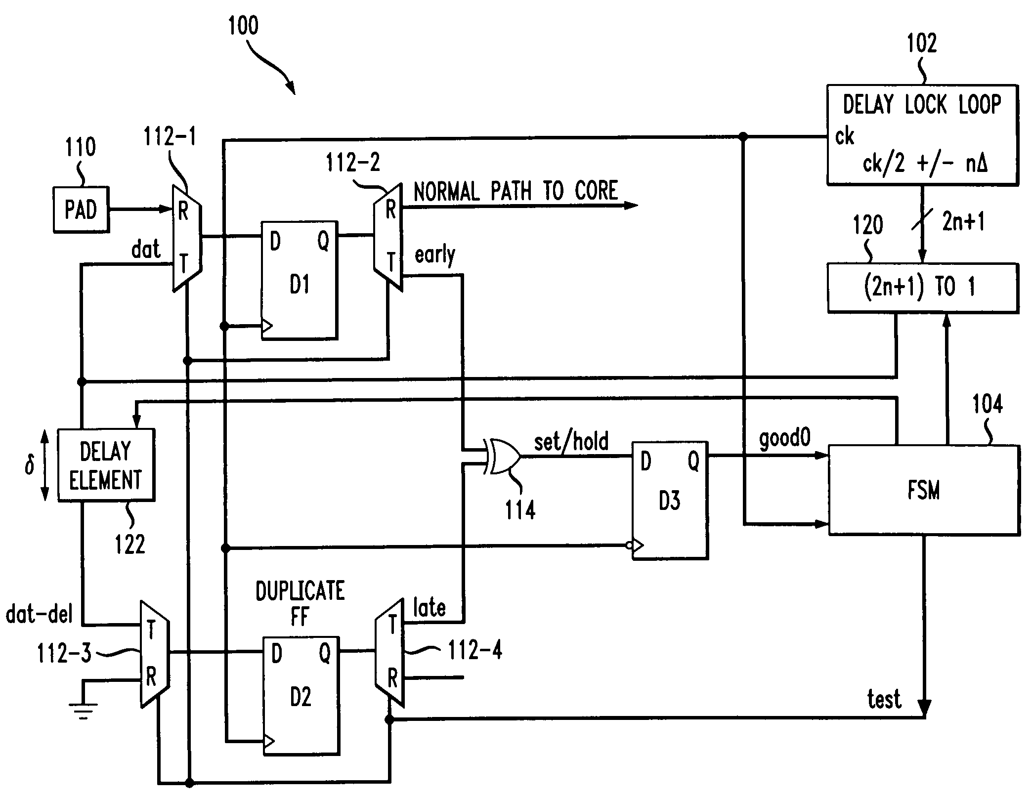
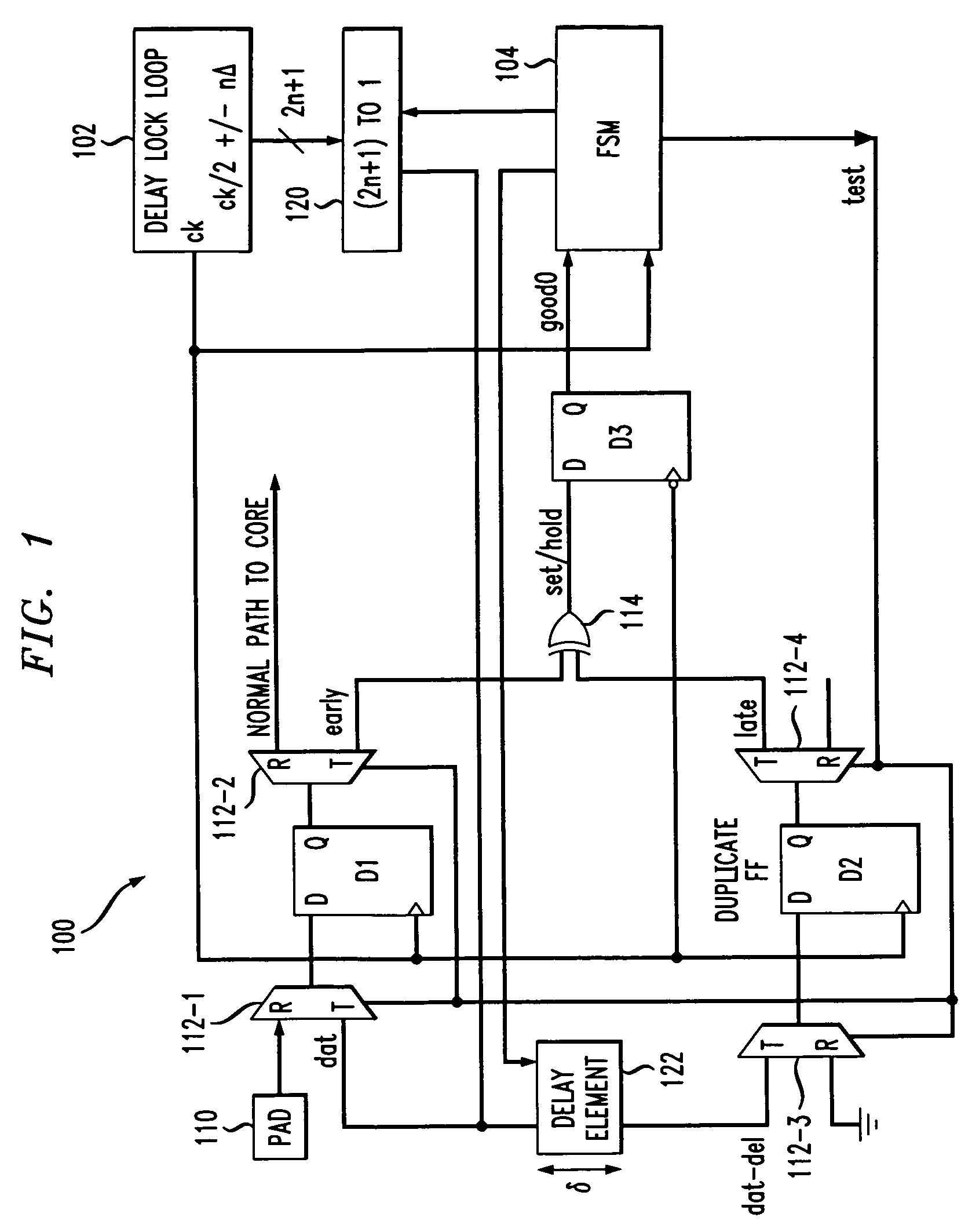
[0019]FIG. 1 shows a data capture circuit 100 with self-test capability in accordance with a first illustrative embodiment of the invention. The data capture circuit 100 in this embodiment includes three data capture elements in the form of D-type flip-flops D1, D2 and D3, a delay lock loop (DLL) 102, a finite state machine (FSM) 104, an in...


PUM


Abstract

A data capture circuit having a self-test capability includes a first data capture element to be tested in a self-test mode of operation, at least one additional data capture element, e.g., a second data capture element that is a substantial duplicate of the first, a clock generator circuit, a controller and a comparison circuit. The clock generator circuit is configured to generate a clock signal for application to clock inputs of the data capture elements, and a number of selectable clock-based test data signals. In the test mode, the controller selects at least a particular one of the test data signals for application to a data input of the first data capture element. A delayed version of the selected test data signal is applied to a data input of the second data capture element. The comparison circuit is configured to compare output signals generated by the first and second data capture elements, and supplies a result of the comparison back to the controller. The controller repeats the selection of particular test data signals and monitors corresponding comparison results until set-up and hold times or other clocking characteristics of the first data capture element are determined to a desired level of accuracy.

Description

FIELD OF THE INVENTION[0001]The present invention relates generally to electronic data capture circuits, such as circuits which include one or more flip-flops, memory cells or input latches, and more particularly to techniques for measuring the ability of such circuits to capture data.BACKGROUND OF THE INVENTION[0002]As is well known, data capture circuits are commonly used in a wide variety of integrated circuit applications. A significant drawback of conventional data capture circuits is the difficulty associated with measuring the ability of such circuits to capture data. For example, flip-flops, memory cells, latches and other data capture elements of such circuits often have minimum requirements for set-up and hold times. The set-up time refers generally to the period of time that the data must maintain a particular logic level at a circuit input prior to clocking, while the hold time refers to the amount of time that the data must remain at the particular level at the circuit ...

Claims


Application Information

Patent Timeline
IPC IPC(8): H04L7/00G01R31/317G01R31/3185G11C7/10G11C29/50
CPCG01R31/31725G01R31/318525G11C7/1078G11C29/50012G11C29/028G11C29/12015G11C29/50G11C7/1087
Inventor GABARA, THADDEUS JOHN
Owner AGERE SYST GUARDIAN
Features
  • R&D
  • Intellectual Property
  • Life Sciences
  • Materials
  • Tech Scout
  • Unparalleled Data Quality
  • Higher Quality Content
  • 60% Fewer Hallucinations
Learn More