Adjustment of a phase difference between two signals

a phase difference and signal technology, applied in the direction of synchronisation signal speed/phase control, instruments, transmission monitoring, etc., can solve the problem of limited control range in which the tracking loop is able to maintain or achieve synchronization, etc., to achieve increased controllability of the tracking loop, wide effective control range, and higher power consumption

Inactive Publication Date: 2007-03-20
NOKIA CORP
View PDF18 Cites 6 Cited by
  • Summary
  • Abstract
  • Description
  • Claims
  • Application Information

AI Technical Summary

Benefits of technology

[0020]It is an advantage of the invention that the wider effective control range achieved for signals having a low signal-to-noise ratio can maintain a tracking loop for a longer time in a lock state. Thus, the controllability of the tracking loop is increased.
[0021]Further, an acquisition or a reacquisition process, which has a higher power consumption than the tracking process, is needed less frequently. By reducing the number of required acquisition and reacquisition processes, a system making use of the invention is also more reliable. This is of particular interest, for instance, for a navigation with terminals performing a satellite based navigation in urban, sub-urban or forested areas, etc.
[0022]In an advantageous embodiment, statistical characteristics of noise, e.g. Gaussian noise, are reflected in the measurement values, in case noise is present in the received signal. In a further ad

Problems solved by technology

The control range in which the tracking loop is able to

Method used


Image

  • Adjustment of a phase difference between two signals
  • Adjustment of a phase difference between two signals
  • Adjustment of a phase difference between two signals

Examples


Embodiment Construction

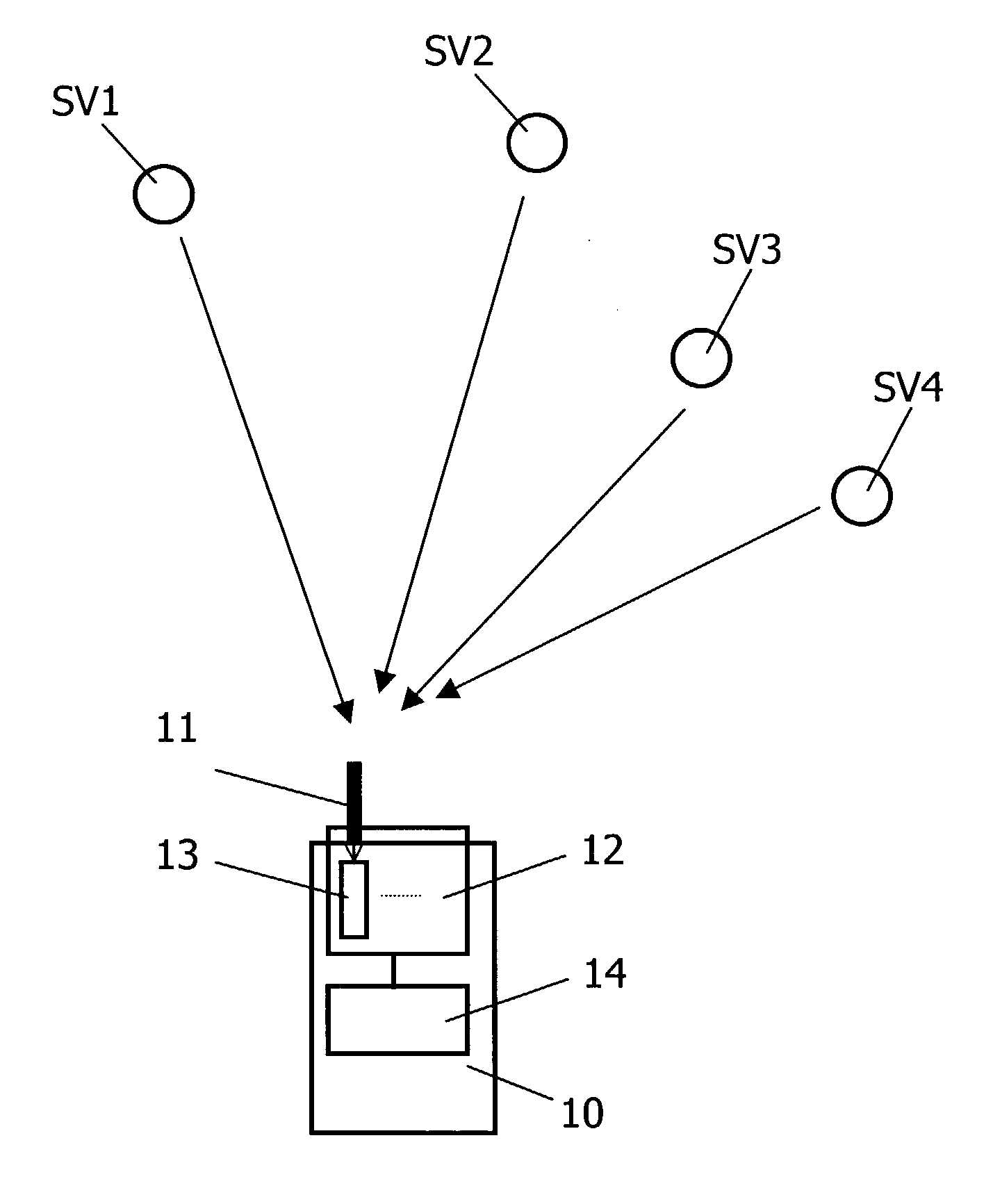
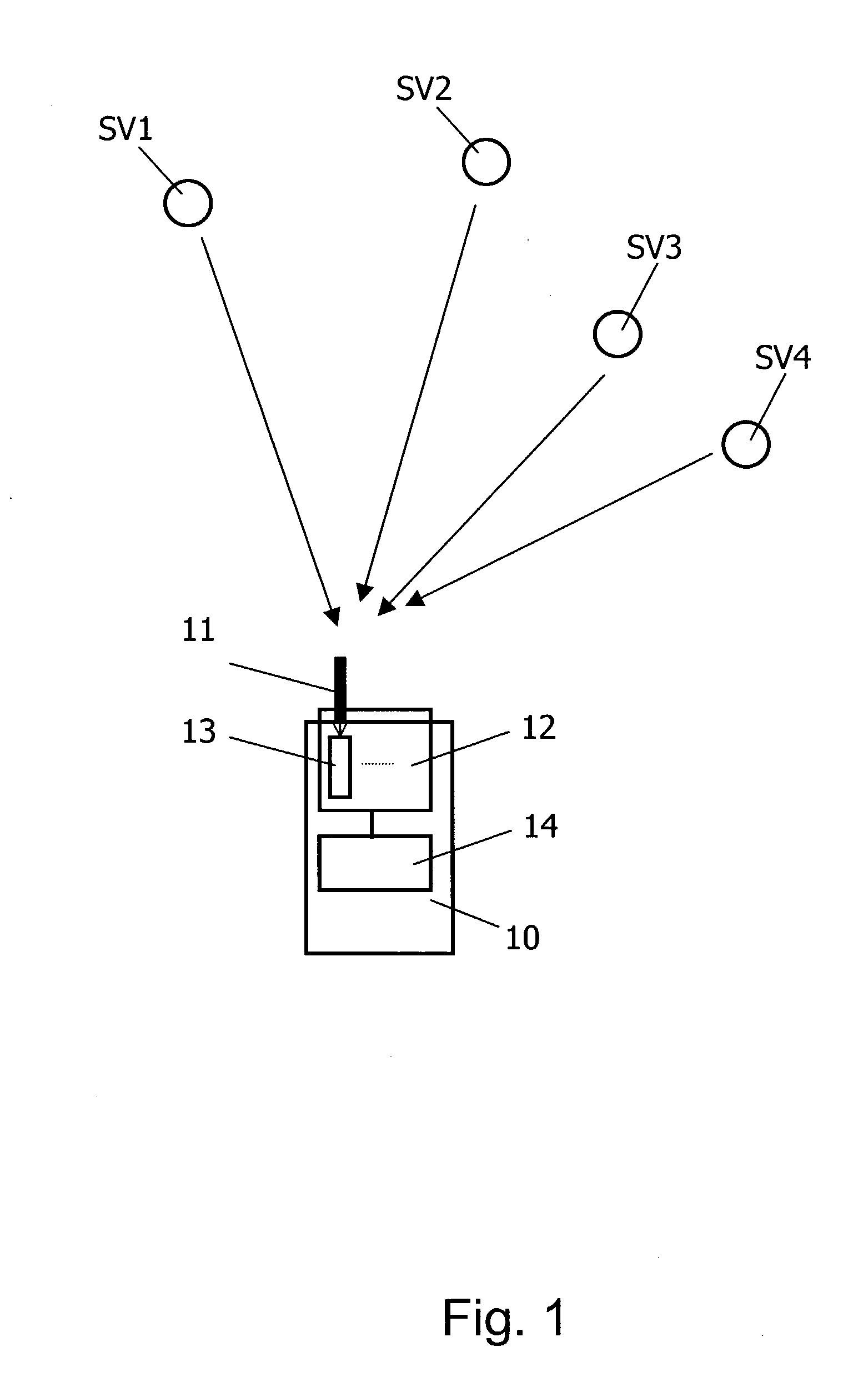
[0033]FIG. 1 schematically presents a positioning system in which the invention is implemented.

[0034]The positioning system comprises a plurality of GPS satellites SV1, SV2, SV3, SV4 and a GPS receiver 10.

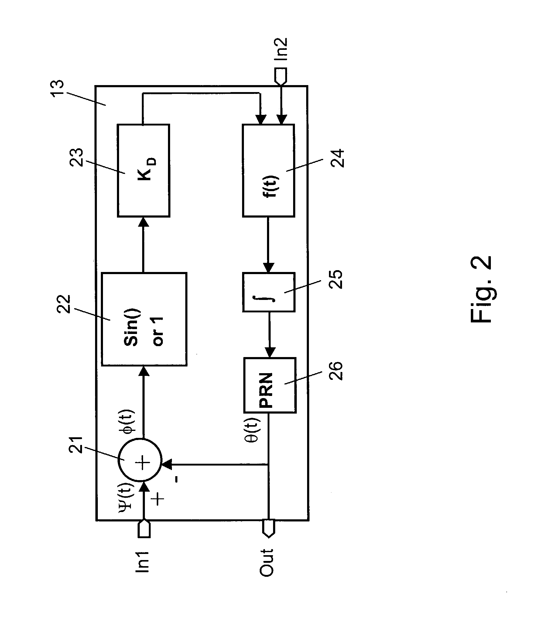
[0035]The GPS receiver 10 comprises an antenna 11, which is connected to a tracking module 12. The tracking module 12 comprises several tracking loops 13, of which only one is depicted in FIG. 1. Each tracking loop 13 forms part of a distinct processing channel for the received signals. Each tracking loop includes a PRN generator for generating a replica code sequence for signals from another GPS satellite. Usually, more than seven tracking loops are provided, i.e. replica code sequences for more than seven satellites can be generated. The output of the tracking module 12 is provided for further use to some other processing components 14.

[0036]When the GPS receiver 10 receives a signal from a satellite SV1, SV2, SV3, SV4, the GPS receiver 10 compares the code values of the received...


PUM


Abstract

A method for adjusting a phase difference between a received code modulated signal and a replica code sequence where, in order to enlarge the control range, it comprises a step of determining measurement values representing a phase difference between a received code modulated signal and a generated replica code sequence. The proposed method further comprises determining coefficients for a loop filter operation, which coefficients optimize a predetermined function specified for current properties of the received signal. Then, a loop filter operation is applied to the measurement values to obtain an indication of a required correction of a current frequency of the generated replica code sequence, which loop filter operation utilizes the determined coefficients. Finally, the frequency of the generated replica code sequence is adjusted based on the indication of a required correction. The invention relates equally to a corresponding unit and to a corresponding system.

Description

FIELD OF THE INVENTION[0001]The invention relates to a method for adjusting the phase difference between a received code modulated signal and a generated replica code sequence. The invention relates equally to a unit and a system for adjusting the phase difference between a received code modulated signal and a generated replica code sequence.BACKGROUND OF THE INVENTION[0002]Adjusting the phase difference between a received code modulated signal and a generated replica code sequence can be used in particular for minimizing the phase difference between the signals, in order to align the generated replica code sequence with the received code modulated signal. This is required for example in CDMA (Code Division Multiple Access) spread spectrum communications.[0003]For a spread spectrum communication in its basic form, a data sequence is used by a transmitting unit to modulate a sinusoidal carrier and then the bandwidth of the resulting signal is spread to a much larger value. For spread...

Claims


Application Information

Patent Timeline
IPC IPC(8): H04B7/01H04B7/00G01S1/00H03L7/107
CPCG01S19/29H04B1/7087H04B1/7085H03L7/107G01S19/30H03L7/1075
Inventor MANNERMA, JARI
Owner NOKIA CORP
Why Eureka
Try Eureka