
Method and apparatus for high accuracy distributed time synchronization using processor tick counters

a time synchronization and processor technology, applied in the direction of digital transmission, generating/distributing signals, instruments, etc., can solve the problem of tens of milliseconds of accuracy of such a synchronization protocol

Inactive Publication Date: 2007-03-20
INTEL CORP
View PDF8 Cites 16 Cited by
  • Summary
  • Abstract
  • Description
  • Claims
  • Application Information

AI Technical Summary

Benefits of technology

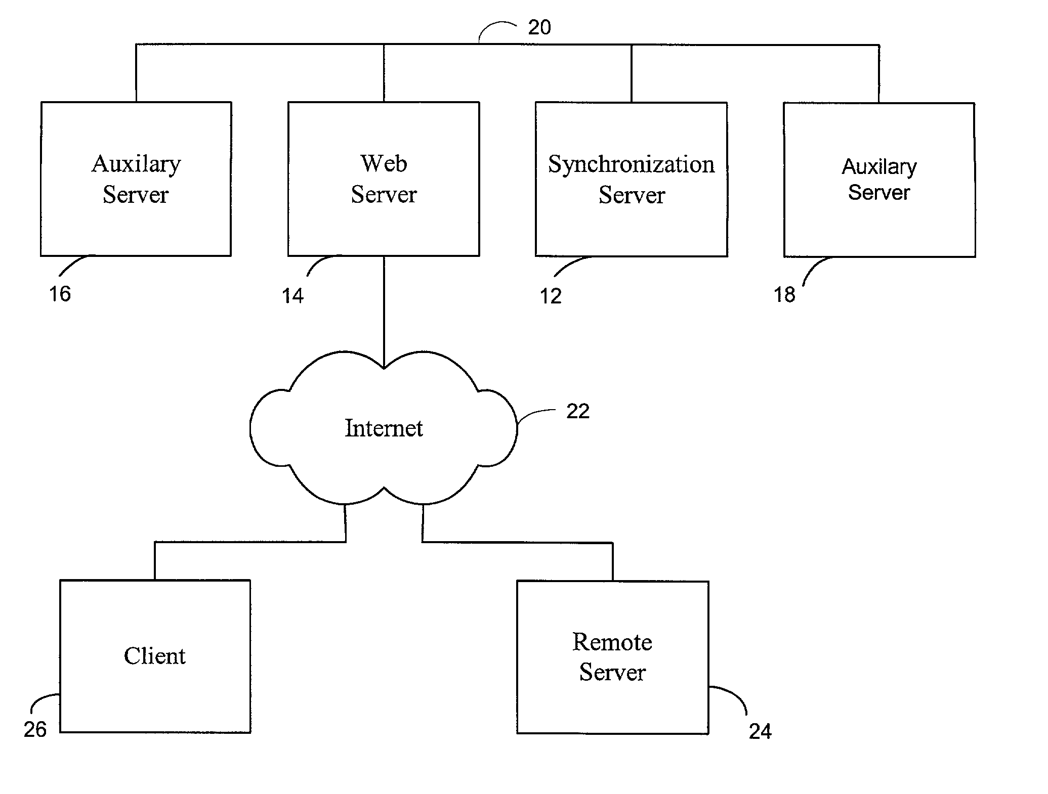
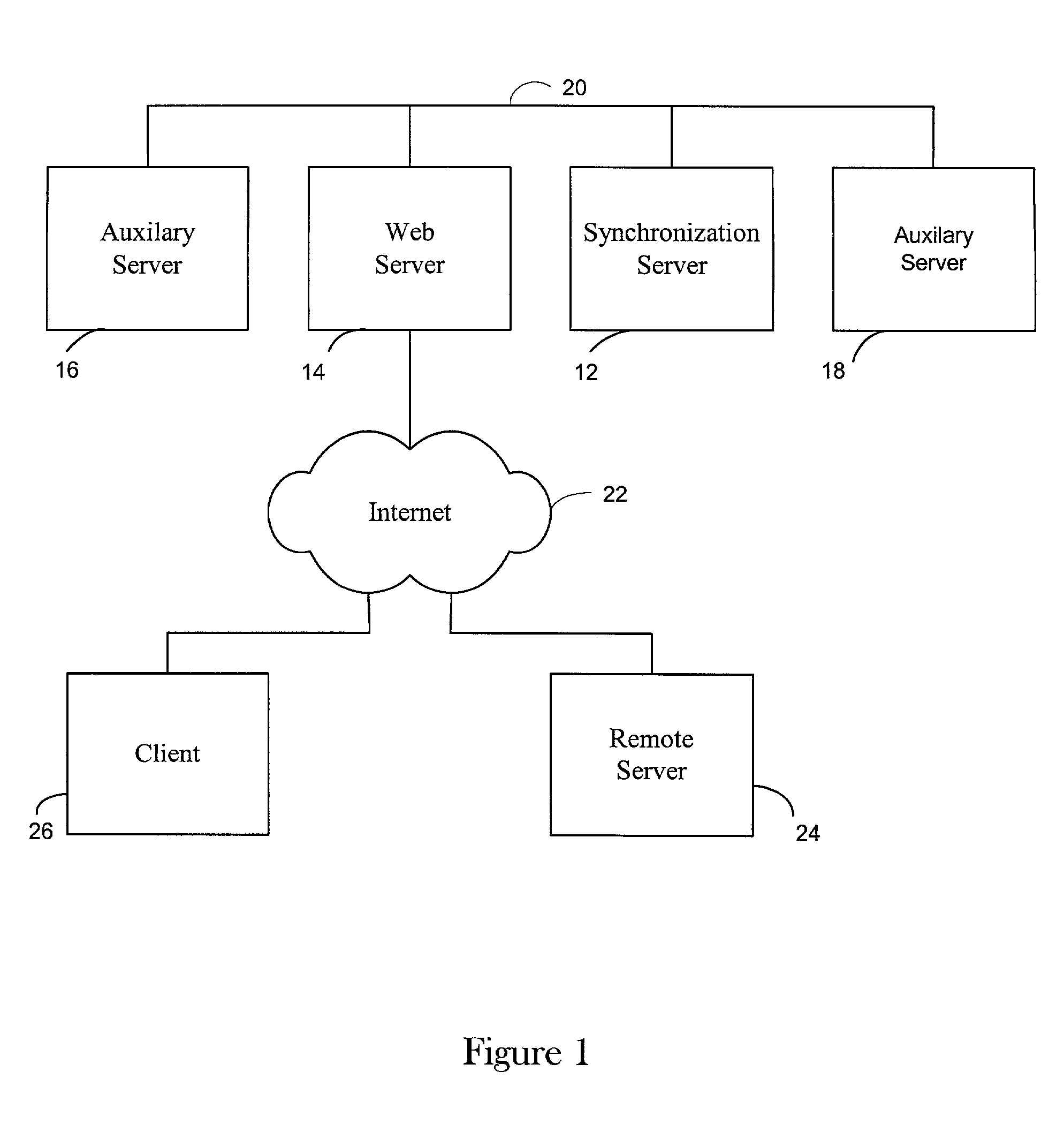
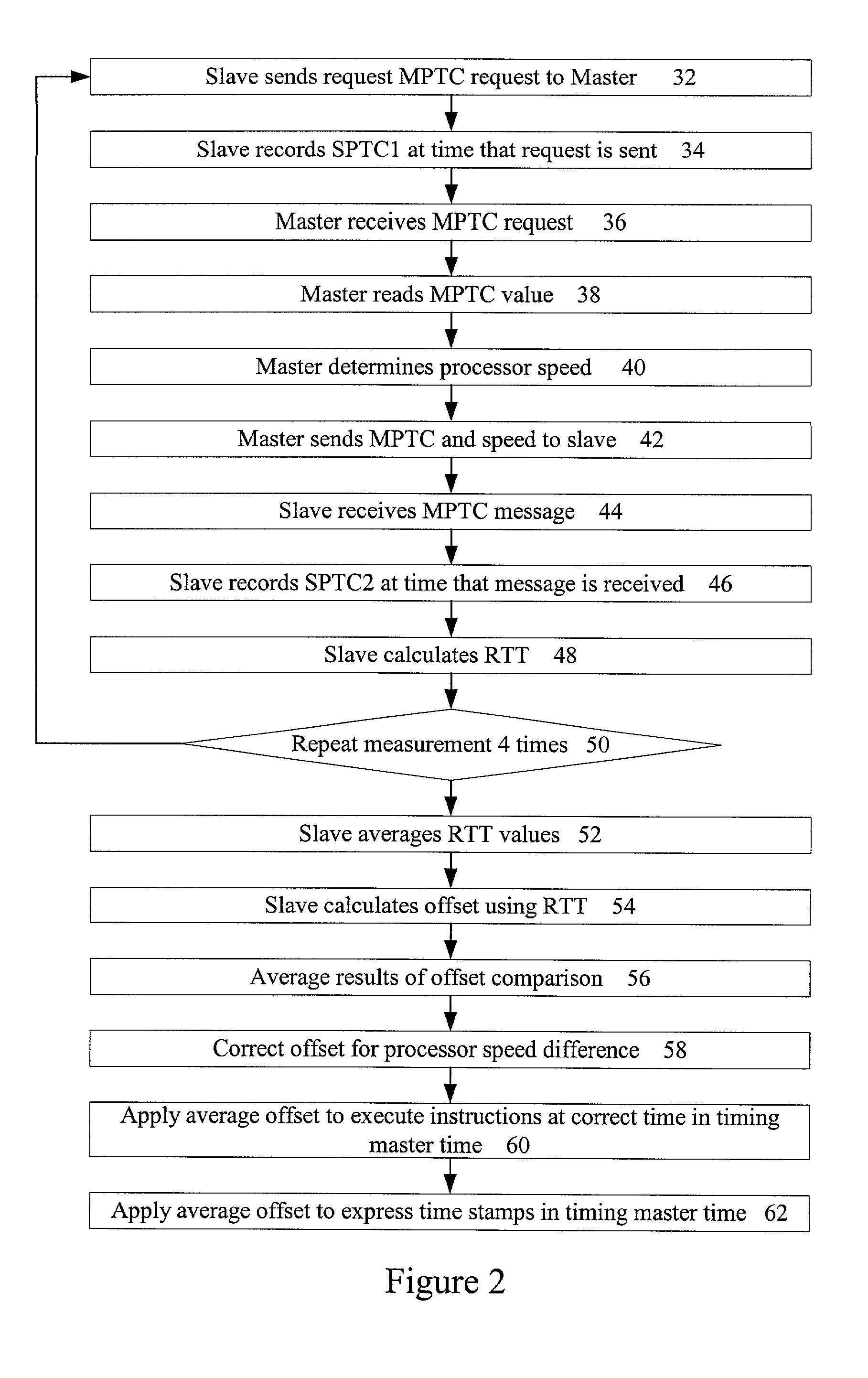
[0014]The present invention allows two separate processing engines, such as microprocessors, for example in two networked computers or in a parallel processing system, to be synchronized with a very high accuracy. The invention can be applied to a variety of systems for a variety of different benefits as discussed above and has a minimal impact on network traffic loads. In one embodiment, the synchronization is applied to microprocessors based on the tick counter of each respective processor. The tick count counter value is maintained in a register of a typical microprocessor and is updated at the speed of the microprocessor. The value can be read from the register with a standard, simple, assembly language instruction. As a result, the value provides very high accuracy commensurate with the processor speed and can be obtained very quickly. For an Intel Pentium® II processor that runs at 233 MHz, synchronization can be obtained with an accuracy on the order of a few nanoseconds. For an Intel Pentium® 4 processor that runs at 1.5 GHz, synchronization can be obtained with an accuracy on the order of half a nanosecond.

Problems solved by technology

Accordingly, the accuracy of such a synchronization protocol is limited to the order of tens of milliseconds or at best milliseconds.

Method used


Image

  • Method and apparatus for high accuracy distributed time synchronization using processor tick counters
  • Method and apparatus for high accuracy distributed time synchronization using processor tick counters
  • Method and apparatus for high accuracy distributed time synchronization using processor tick counters

Examples


Embodiment Construction

[0014]The present invention allows two separate processing engines, such as microprocessors, for example in two networked computers or in a parallel processing system, to be synchronized with a very high accuracy. The invention can be applied to a variety of systems for a variety of different benefits as discussed above and has a minimal impact on network traffic loads. In one embodiment, the synchronization is applied to microprocessors based on the tick counter of each respective processor. The tick count counter value is maintained in a register of a typical microprocessor and is updated at the speed of the microprocessor. The value can be read from the register with a standard, simple, assembly language instruction. As a result, the value provides very high accuracy commensurate with the processor speed and can be obtained very quickly. For an Intel Pentium® II processor that runs at 233 MHz, synchronization can be obtained with an accuracy on the order of a few nanoseconds. For...


PUM


Abstract

A method and apparatus are provided that allow processing engines to be synchronized to each other with high accuracy. In one embodiment, the invention includes obtaining a processor tick counter value from a first processing engine, comparing the obtained processor tick counter value to a processor tick counter value from a second processing engine and determining a timing offset for synchronizing the first processing engine and the second processing engine using the comparison. The invention may further include obtaining a processor tick counter value by sending a request message from the second processing engine to the first processing engine, and receiving a reply from the first processing engine at the second processing engine. The processor tick counter value at the second processing engine can be determined by recording the time at which the request message is sent and by recording the time at which the reply is received. The invention can further include obtaining a processor frequency from the first processing engine, obtaining a processor frequency from the second processing engine and correcting the timing offset for any difference between the first processing engine frequency and the second processing engine frequency.

Description

BACKGROUND OF THE INVENTION[0001]1. Field of the Invention[0002]The present invention relates generally to the field of time synchronization of distributed processors. More particularly, the invention relates to the use of processor tick counter values to determine clock offsets to synchronize timing in networks of distributed processors.[0003]2. Description of the Related Art[0004]Accurate time-stamps and accurate timing synchronization are valuable for many different computing tasks in many environments. Current time synchronization protocols typically use the system clock of each computing resource for synchronization. The system clock is typically an independent component that resides on a system bus or a memory bus. The resolution of system clocks is determined by the interrupt cycle of the clock and is typically on the order of one to ten milliseconds. Accordingly, the accuracy of such a synchronization protocol is limited to the order of tens of milliseconds or at best millis...

Claims


Application Information

Patent Timeline
IPC IPC(8): G06F15/16G06F1/12
CPCG06F1/12
Inventor RAJAGOPAL, PRIYADURHAM, DAVID M.
Owner INTEL CORP
Learn More