Bandpass filter for differential signal, and multifrequency antenna provided with same

a technology of differential signal and filter, which is applied in the direction of waveguides, antenna feed intermediates, antennas, etc., can solve the problems of large effective noise and received noise outside the band, and achieve the effect of small nois

Inactive Publication Date: 2007-03-27
VICETTA PAC CO LLC
View PDF5 Cites 10 Cited by
  • Summary
  • Abstract
  • Description
  • Claims
  • Application Information

AI Technical Summary

Benefits of technology

[0012]According to the present invention, it is possible to provide a bandpass filter for a differential signal applicable to a device having a wide passband, being a device for transmitting a signal using a differential signal such as a self complementary antenna. The bandpass filter for a differential signal of the present invention is small and inexpensive.

Problems solved by technology

For this reason, noise outside the band is also received, and there is a problem of the effective noise becoming large.

Method used


Image

  • Bandpass filter for differential signal, and multifrequency antenna provided with same
  • Bandpass filter for differential signal, and multifrequency antenna provided with same
  • Bandpass filter for differential signal, and multifrequency antenna provided with same

Examples


first embodiment

[0023]A bandpass filter for a differential signal relating to the first embodiment of the invention will now be described with reference to the drawings. First of all, the structure of this bandpass filter for a differential signal will be described, and then theoretical operation of this bandpass filter for a differential signal and its characteristics will be described.

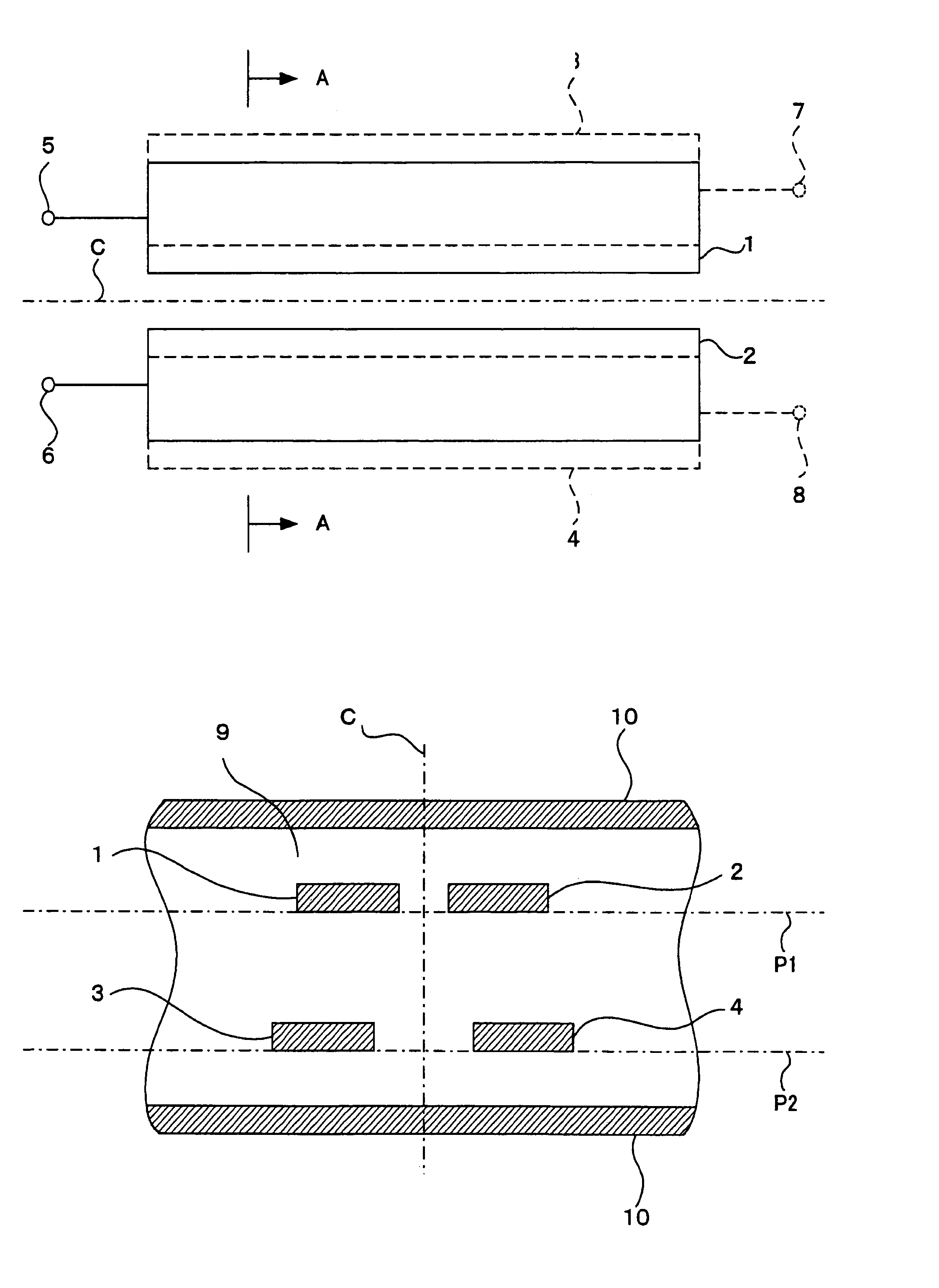
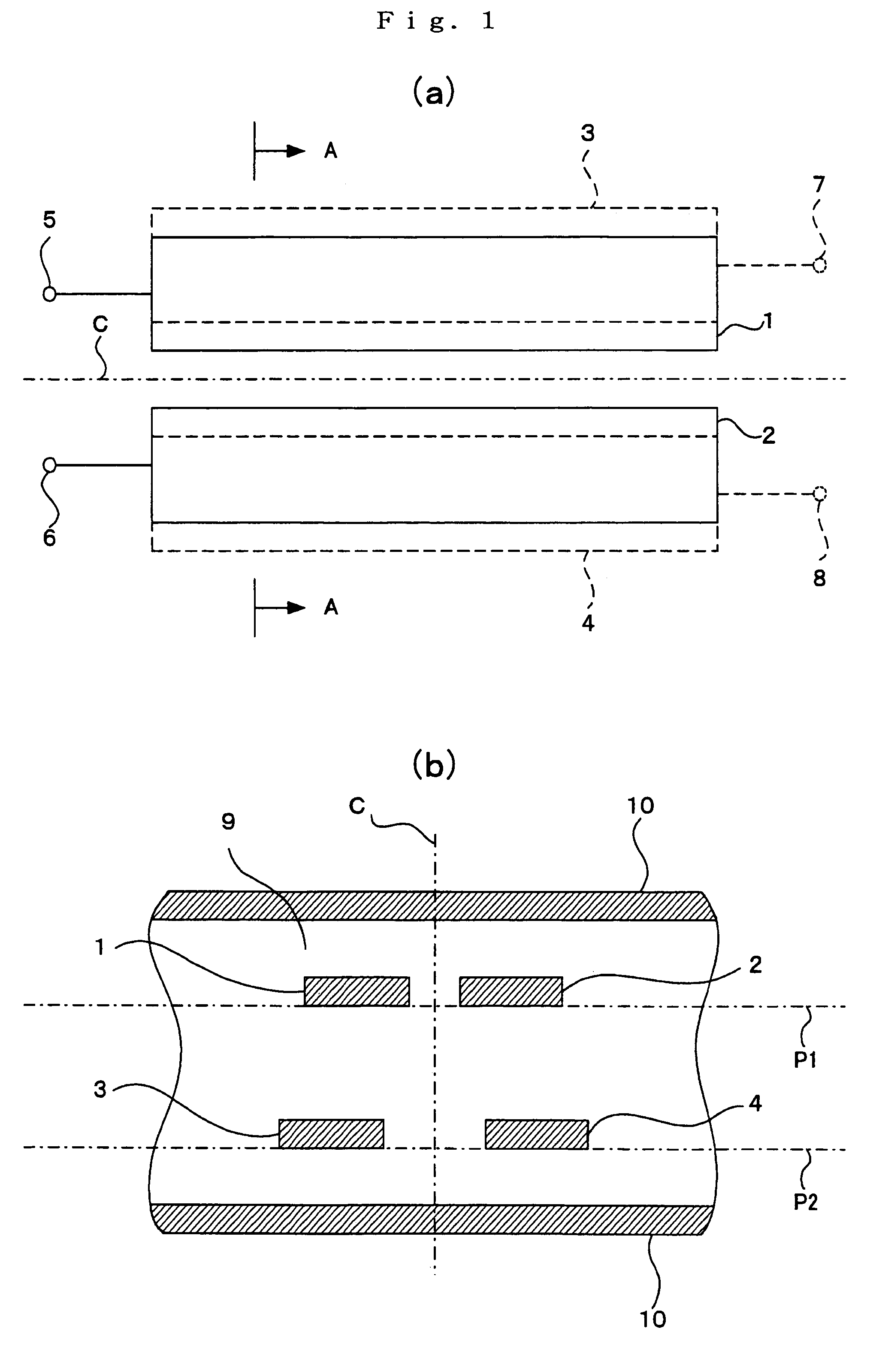
[0024]The structure of the filter relating to the first embodiment of the invention is shown in FIG. 1(a) and FIG. 1(b). FIG. 1(a) is a plan view of the filter, while FIG. 1(b) is a cross sections looking in the direction of arrows A—A in the plan view (arrow A—A cross sectional view). In these drawings, reference numeral 1 is a first line, 2 is a second line, 3 is a third line, and 4 is a fourth line. Reference numeral 5 is an input / output end of the first line 1, while 6 is an input / output end of the second line 2. The input / output ends 5, 6 together form a first differential input / output end. Ends at the opposite...

second embodiment

of the Invention

[0072]UWB communication systems suppress interference with other wireless systems by having small transmission power. However, 5 GHz band wireless LAN systems used between individuals similarly are often in the same room, and in this case, it is confirmed that interference arises. In order to avoid this, a 5–6 GHz band used in a wireless LAN was evaluated so that there was no radio wave output in the UWB. The second embodiment of the invention is used in an intermediate manner in this way, and a band stop filter for steeply cutting off some frequencies within a band of a wideband pass filter of the first embodiment of the invention, and minimizing effects on other bands, is provided in the wideband pass filter of the first embodiment.

[0073]FIG. 5 is a plan view of a wideband filter for a differential signal fitted with a band stop filter of the second embodiment of the invention. In FIG. 5, the same reference numerals are attached to sections that are the same as in ...

third embodiment

the Invention

[0077]A filter of the third embodiment of the invention has two wideband bandpass filters of the first embodiment of the invention cascade-connected, and is provided with a band stop filter for cutting off some frequencies within that band steeply while keeping the effect on other bands to a minimum connected to the cascade connection point. The filter of the third embodiment of the invention has a different structure to embodiments 1 and 2 of the invention.

[0078]FIG. 6 is a plan view of the filter relating to the third embodiment of the invention. Reference numerals 11 and 12 are a first line and a second line arranged on a first surface. The first line 11 and second line 12 have respective line lengths equivalent to about a quarter wavelength of a center frequency of a used band (0.25 wavelengths, 0.75 wavelengths, 1.25 wavelengths, 1.75 wavelengths etc.) but are actually slightly shorter than a quarter wavelength (for example, 1 / 100 of wavelength (0.01) shorter). Ref...


PUM


Abstract

There is provided a bandpass filter for a differential signal applicable to a device having a wide passband, being a device for transmitting a signal using a differential signal. Respective lines 1 and 2 and lines 3 and 4 are provide on two surfaces P1 and P2 at an inner layer of a dielectric body 9. Each two lines are arranged symmetrically about the same plane of symmetry C, and the length of each line is a quarter wavelength at the center frequency of a used band. Reference numerals 5 and 6 are input / output ends of the lines 1 and 2, and 7 and 8 are input output ends of lines 3 and 4. Opposite ends to the input output ends are open. If a differential signal is input to terminals 5, 6, a differential output appears at the terminals 7, 8. This device works as a bandpass filter.

Description

FIELD OF THE INVENTION[0001]This invention relates to a bandpass filter for a differential signal that can be applied to an ultra wideband wireless system capable of high speed transmission, and to a multifrequency antenna provided with a plurality of such bandpass filters.BACKGROUND OF THE INVENTIONDESCRIPTION OF THE RELATED ART[0002]In recent years, close range wireless interfaces such as wireless LANs and Bluetooth (trademark) have become widely used, but ultrawideband wireless systems (UWB) have been receiving even greater attention as the next generation of systems to enable even higher speed transmission. Specification investigations are currently progressing in various countries, but it is recognized that the usage frequency for these UWB systems in the US is 3.1–10.6 GHz with a comparatively large output. This UWB system is capable of high-speed wireless transmission at 100 Mbps or above due to use of frequencies in an extremely wide band.[0003]An antenna using the above-des...

Claims


Application Information

Patent Timeline
Patent Type & Authority Patents(United States)
IPC IPC(8): H01P1/203H01P1/205H01P1/213H01Q5/10H01Q9/28
CPCH01P1/2039H01P1/203H03H7/0161
Inventor SAITOU, AKIRAHONJO, KAZUHIKO
Owner VICETTA PAC CO LLC
Why Eureka
Try Eureka