Image processing device, printing control device, image processing method, and recorded medium

a technology of image processing and printing control, which is applied in the direction of image enhancement, digital output to print units, instruments, etc., can solve the problems of time-consuming, inability to conduct simultaneous dot on-off state determination for all pixels, and inability to quickly carry out dot on-off state determination, etc., to achieve the effect of shortening the processing tim

Active Publication Date: 2007-03-27
SEIKO EPSON CORP
View PDF17 Cites 14 Cited by
  • Summary
  • Abstract
  • Description
  • Claims
  • Application Information

AI Technical Summary

Benefits of technology

[0096]FIG. 13 is an explanatory drawing showing the principle of shortening processing time by performing parallel processing of multiple rasters in the tone number conversion routine of a second embodiment;

Problems solved by technology

In both of these methods, because the image comprises a large number of pixels, it is impossible to conduct the dot on-off state determination simultaneously for all pixels.
However, in these methods, the problem exists that binarization errors arising each time a dot on-off state determination is conducted must be written to the buffer frequently, which means that the dot on-off state determination cannot be carried out quickly.
In either case, dot on-off state determination is time-consuming to the extent that reading and writing to and from the buffer must be carried out frequently.
Where dot on-off state determination takes a long time, it becomes difficult to display image rapidly.

Method used


Image

  • Image processing device, printing control device, image processing method, and recorded medium
  • Image processing device, printing control device, image processing method, and recorded medium
  • Image processing device, printing control device, image processing method, and recorded medium

Examples


first embodiment

B.

B-1. Apparatus Construction:

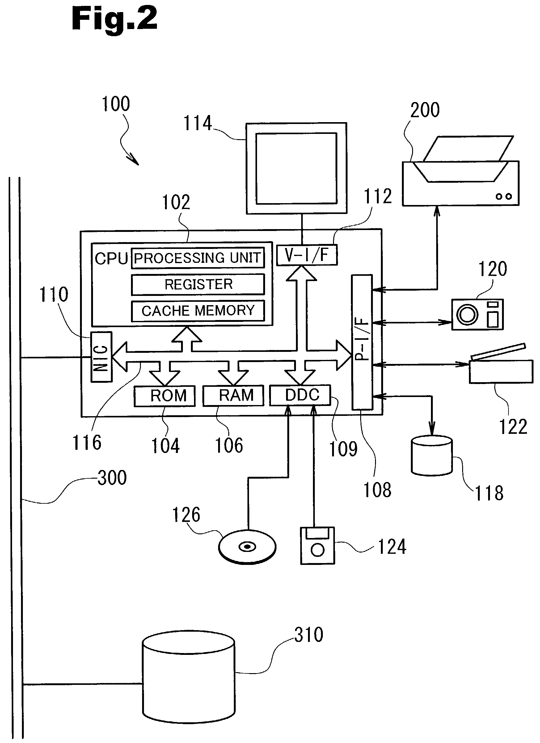
[0114]FIG. 2 is an explanatory drawing showing the construction of a printer 100 comprising the image processing apparatus of the first embodiment. The computer 100 is a conventional computer centered around a CPU 102, wherein a ROM 104 and a RAM 106 are interconnected via a bus 116. The CPU 102 comprises a processing unit that performs actual processing and multiple registers in which data is temporarily stored during processing. The data stored in the registers can be processed much more quickly than the data stored in the RAM 106.

[0115]A disk controller DDC 109 used to read data from a floppy disk 124 or a compact disk 126, a peripheral equipment interface P-I / F 108 used to send and receive data to and from peripheral equipment, a video interface V-I / F 112 used to drive a CRT 114 and the like are connected to the computer 100. A color printer 200 described below, a hard disk 118 and the like are connected to the P-I / F 108. Furthermore, if a digital c...

first modification

(1) First Modification

[0164]The description above involved the simplest possible example, wherein dot on-off state determination was conducted for two rasters in a parallel manner. However, the number of rasters that may be processed in a parallel manner is not limited to two, and may comprise three or more. FIG. 9 is an explanatory drawing showing a conceptual view of the situation in which dot on-off state determination is conducted for three rasters in a parallel manner. In FIG. 9, dot on-off state determination is conducted for the three rasters (i), (j) and (k) in a parallel manner. In order to avoid making the description unduly complex, the error diffusion matrix shown in FIG. 6(a) is used here, as in the case shown in FIG. 7.

[0165]The hatched lines in the raster (i) and the raster (k) indicate that diffused errors allocated to these raster pixels are stored in the RAM 106. The numbers enclosed by circles located inside the pixels of the rasters (i), (j) and (k) indicate the ...

second embodiment

C.

[0178]In the various embodiments described above as the tone number conversion routine of the first embodiment, the binarization error occurring during dot on-off state determination for the target pixel was diffused into and stored in connection with surrounding pixels in accordance with error diffusion coefficients set in an error diffusion matrix. This means that the method of the first embodiment can be presumed to conform to the so-called error diffusion method. Dot on-off state determination for multiple rasters can also be conducted in a parallel manner using a method conforming to the so-called average error minimum method. The tone number conversion routine of this second embodiment will be explained below.

C-1. Tone Number Conversion Routine of the Second Embodiment:

[0179]FIG. 13 is an explanatory drawing to explain in a conceptual manner the principle by which dot on-off state determination is conducted quickly through parallel processing of multiple rasters in the tone ...


PUM


Abstract

When image data is converted into an expression format based on the dot on-off state, such conversion is performed in a unit of a raster group comprising a predetermined number of adjacent rasters. When this is done, the binarization errors occurring in each pixel of the last raster located in the last position of such raster group are diffused into surrounding pixels and stored in a first storage unit. The errors are read out from the first storage unit for dot on-off state determination regarding the first raster of the raster group adjacent to the above-mentioned last raster, and binarization errors occurring in connection with this determination are stored in a second storage unit that permits faster reading and writing of data than the first storage unit. The remaining rasters following the first raster are converted into dot rows by conducting dot on-off state determination for each pixel therein in parallel with the process to convert the first raster into a dot row while taking into account the binarization errors that occurred in the first raster. Consequently, the errors that are taken into account by the pixels of the same raster are stored in the second storage unit that permits faster high-speed reading and writing of data, and the image data for the raster group can be converted at a high speed.

Description

TECHNICAL FIELD[0001]This invention relates to a technology for converting image data that is expressed in terms of tone values for multiple pixels included in an image, and more particularly, to a technology for converting this image data to image data using a specific expression format that is based on the dot on-off state of each pixel.BACKGROUND ART[0002]Image display apparatuses that express images through the formation of dots on a display medium such as a printing medium or a liquid crystal display are widely used as output devices for various types of image equipment. These image display apparatuses can only express images locally in terms of whether or not a dot is formed, but by appropriately controlling the density of dot formation in accordance with the tone values of the image, images in which the tone changes gradually can be expressed.[0003]In these types of image display apparatuses, the methods by which to determine the dot on-off state for each pixel in order to fo...

Claims


Application Information

Patent Timeline
Patent Type & Authority Patents(United States)
IPC IPC(8): G06K15/00H04N1/40H04N1/405G09G5/00G06T5/00
CPCH04N1/4052H04N1/60
Inventor KAKUTANI, TOSHIAKI
Owner SEIKO EPSON CORP
Why Eureka
Try Eureka