Optical head

a technology of optical heads and optical heads, applied in the field of optical heads, can solve the problems of increasing the recording density of a the size and dynamic performance of the development of a small optical head corresponding to the small diameter optical disk, so as to achieve the effect of reducing the size of the optical head, preventing the imbalance of dynamic performance, and improving dynamic performan

Inactive Publication Date: 2007-03-27
SONY CORP
View PDF11 Cites 29 Cited by
  • Summary
  • Abstract
  • Description
  • Claims
  • Application Information

AI Technical Summary

Benefits of technology

[0039]In the optical head according to the present invention, a magnetic circuit for generating a driving force in the tracking direction and focus direction without disposing the two pairs of magnets on the Y axis orthogonal to the optical axis of the objective lens can be formed. Therefore, the size of the optical head can be reduced in the Y axis direction.
[0040]Each pair of magnets is disposed plane-symmetrically to the Z-Y plane including the Z axis aligned with the optical axis of the objective lens and the Y axis, and the magnets magnetized in the Y axis direction are disposed so that the surfaces opposing the tracking coils are the same pole. Therefore, imbalance of the dynamic performance can be prevented because the center of gravity of the movable parts including the coil bobbin and the objective lens, the driving point of the focus (tracking), and the support point of the focus (tracking) align on the focus (tracking) axis, and the dynamic performance can be easily improved as the density and transfer rate are increased.

Problems solved by technology

There are several technical difficulties in increasing the recording density of a small diameter optical disk used for portable apparatuses.
One difficulty is to develop a small optical head corresponding to the small diameter optical disk.
As described above, although a reduction in size and dynamic performance are required for the two-axis actuator, or, in other words, the optical head, that is used for an optical disk with a small diameter and a high recording density, known optical heads cannot meet these requirements.
By reducing the size, however, a secondary resonance of the movable parts including the objective lens and the coil bobbin decreases and the dynamic performance becomes unbalanced because of the difference in the positions of the center of gravity, the driving point, and the support point, making it difficult to improve the performance of the optical head.
In such a case, however, the linearity in the fine driving is not maintained because of the friction between the shaft and the shaft hole on the bobbin.
Therefore, there is a problem in that the optical head is not suitable for an optical disk system with small defocusing and detracking margins.

Method used


Image

  • Optical head
  • Optical head
  • Optical head

Examples


Embodiment Construction

[0051]Embodiments of the present invention will be described in detail below by referring to the drawings.

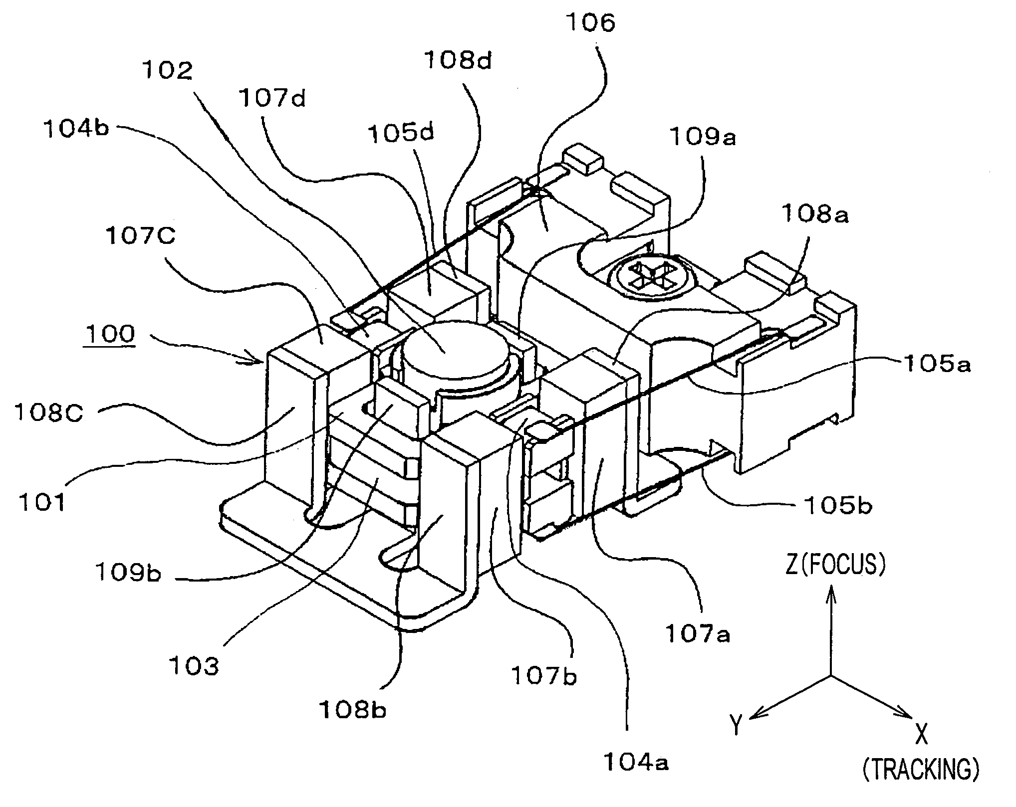
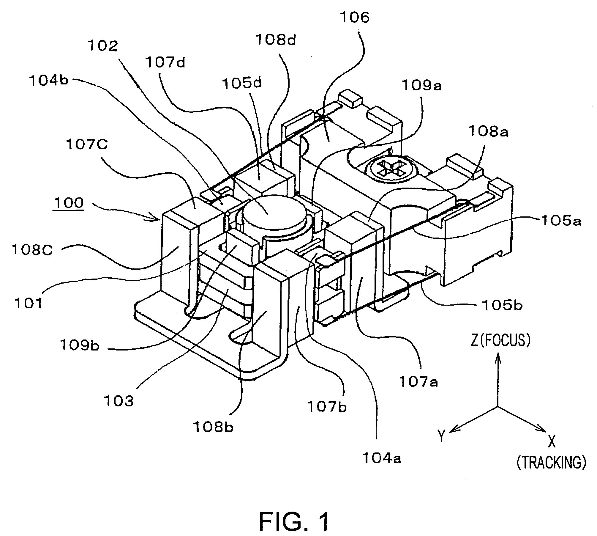
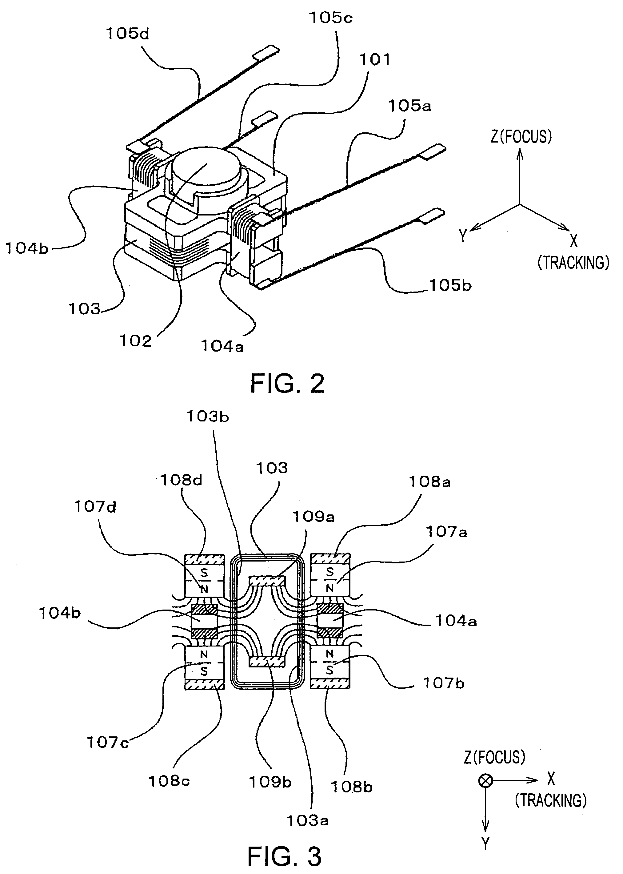
[0052]FIG. 1 is a perspective view illustrating an embodiment of an optical head according to the present invention. FIG. 2 is a perspective view of a coil bobbin, focusing coil, and tracking coils of an optical head according to an embodiment. FIG. 3 is a schematic view of the magnetic field distribution of magnets according to an embodiment. FIG. 4 is a descriptive perspective view of a focusing coil and tracking coils according to an embodiment. FIG. 5 is a schematic view of the driving principle of an optical head according to an embodiment.

[0053]In FIGS. 1 and 2, the reference numeral 100 indicates a two-actuator optical head that can compensate for surface deflection and decentering of an optical disk by driving an objective lens vertically with respect to the surface of the optical disk, that is, along the Z axis in the focus direction and in the radial direction of the o...


PUM

PropertyMeasurementUnit
diameteraaaaaaaaaa
optical axisaaaaaaaaaa
polarityaaaaaaaaaa

Abstract

An optical head enabling a size reduction so that the optical head can be stored in an opening of a cartridge for a disk and enabling an improvement in the dynamic performance as the density and transfer rate are increased is provided. In a two-axis actuator optical head capable of driving an objective lens (102) along the Z axis in the focus direction, that is, vertical to the surface of the optical disk and along the X axis in the tracking direction, that is, the radial direction of the optical disk. The objective lens (102) is disposed in the center of the coil bobbin (101), a focusing coil (103) is disposed around the coil bobbin (101) and is wound around the X axis, and tracking coils (104a and 104b) are disposed on both ends of the coil bobbin (101) in the X axis direction and are wound around the X axis. Pairs of magnets (107a to 107d) are disposed plane-symmetrically with the Z-Y plane including the Z axis aligned with the optical axis of the objective lens (102) and the Y axis and with the Z-X plane including the Z axis and the X axis.

Description

TECHNICAL FIELD [0001]The present invention relates to an optical head used for an optical pick-up such as a magnetic optical disk apparatus or a DVD apparatus, and, more specifically, the invention relates to an optical head capable of realizing a high recording density and small diameter optical disk system, wherein the optical head is a two-axis actuator optical head capable of moving an objective lens in two axial direction, i.e., the focusing direction and the tracking direction.BACKGROUND ART[0002]Recently, along with the advancement of basic technology, the development of optical disks originating from compact disks (CDs) has lead to a significant increase in the memory size per unit area of the disk. This typical basic technology includes shortening the frequency of the light source, increasing the numerical aperture of the objective lens, and developing a more efficient recording mode.[0003]Such an increase in the recording density of an optical disk has led to innovative n...

Claims


Application Information

Patent Timeline
Patent Type & Authority Patents(United States)
IPC IPC(8): G11B7/00G11B7/09G11B7/1369G11B7/1392
CPCG11B7/0932G11B7/13925G11B7/0935G11B7/1369G11B7/0933G11B7/093G11B7/09G11B7/1378
Inventor IIDA, ATSUSHIWATANABE, TOSHIOTANASE, HIRONOBUYAMAMOTO, KENJIHASHIMOTO, GAKUJI
Owner SONY CORP
Why Eureka
Try Eureka