Particle-optic electrostatic lens

a technology of electrostatic lens and optical lens, which is applied in the field of electrostatic lens improvement, can solve the problems of affecting affecting the quality of the structure formed on the target, and affecting the effect of the optical aberration, so as to facilitate the magnetic shielding of the electrostatic lens system and reduce the space the lens occupies

Active Publication Date: 2007-04-03
IMS NANOFABTION
View PDF18 Cites 31 Cited by
  • Summary
  • Abstract
  • Description
  • Claims
  • Application Information

AI Technical Summary

Benefits of technology

[0006]It is an aim of the present invention to facilitate the magnetic shielding of an electrostatic lens system, in particular by reducing the space the lens occupies.
[0008]The use of multi-electrode columns to replace the electrostatic lenses which, so far, included only a small number of electrodes as far as particle-beam exposure devices are concerned, offers a considerable reduction in the space needed for the electrodes. Furthermore, the provision of outer portions with corresponding surfaces which oppose each other allows to enhance magnetic shielding of the device since the lateral dimension of the electrodes can be chosen according to the dimensions of the other components of the particle-beam device.
[0012]A suitable shaping of the electrodes is realized by providing one outer portion of the electrodes mainly for shielding out external fields, while an inner portion is designed to shape the electrostatic field inside the lens. According to this concept, each electrode of the electrode column comprises an outer member ring having a cylindrical shape with corresponding opposing surfaces facing toward the next and previous electrodes, respectively, and further comprises an inner member ring with a circular edge directed toward the optical axis. In an advantageous variant for avoiding secondary electron effects, the inner member ring may be provided with a concave surface extending outward from the circular edge and facing toward the direction from where the charged particles enter the electrode column.

Problems solved by technology

Due to their nature, the performance of electrostatic lenses is gravely affected by electromagnetic fields that are generated in the surroundings of the apparatus and may enter the apparatus where it causes a deviation of the charged particles from the desired path, resulting in optical aberrations which deteriorate the quality of the structures formed on the target.
In particular the shielding of magnetic fields—including the earth magnetic field—is an important issue in the layout of lithography devices.
Since the handling of voluminous shields is difficult and soft-magnetic materials are expensive, the shielding of charged-particle device is problematic due to the large size of the components—in particular electrostatic lenses—of those devices.

Method used


Image

  • Particle-optic electrostatic lens
  • Particle-optic electrostatic lens
  • Particle-optic electrostatic lens

Examples


Embodiment Construction

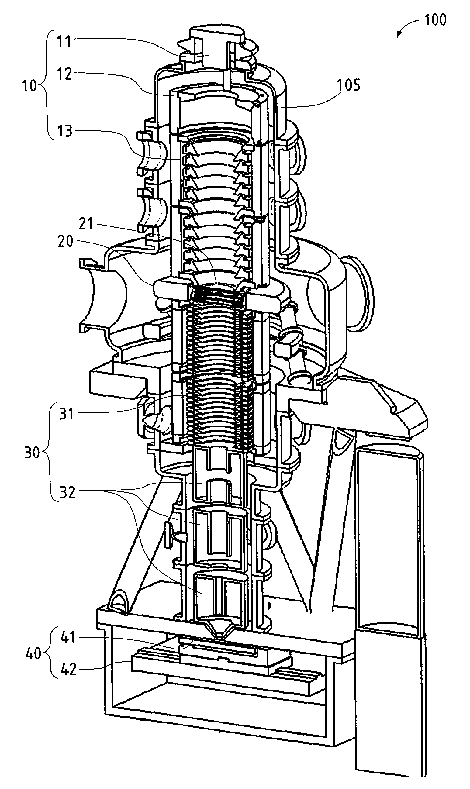
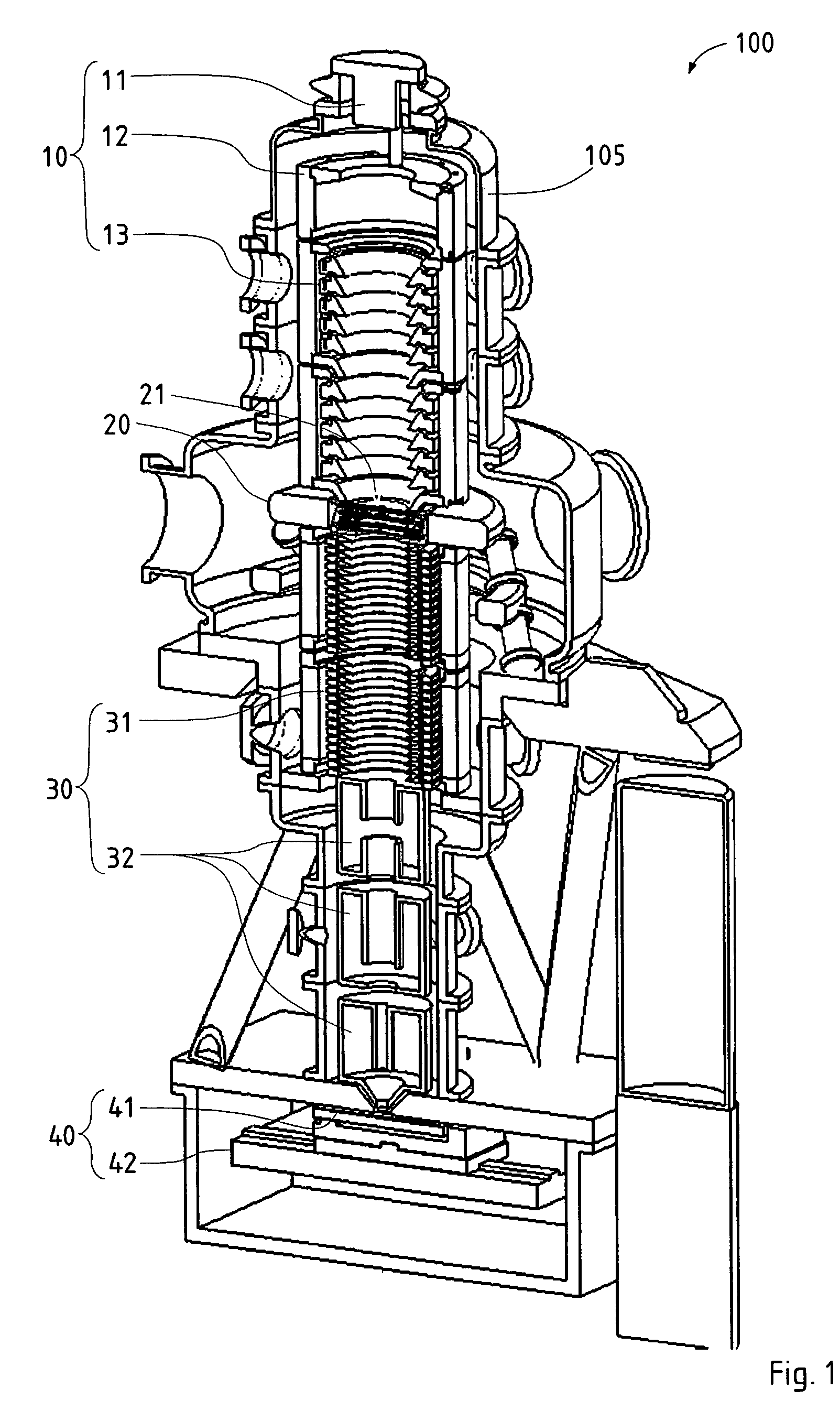
[0022]An overview of an charged-particle-beam lithographic apparatus 100 employing a preferred embodiment of the invention is shown in FIG. 1. In the following, only those details are given as needed to disclose the invention. The main components of the lithography apparatus 100 are—corresponding to the direction of the electron beam which runs vertically downward in FIG. 1—an illumination system 10, a pattern definition system 20, a projecting system 30, and a target station 40 comprising the substrate 41. The whole apparatus 100 is contained in a vacuum housing 105 held at high vacuum to ensure an unimpeded propagation of the beam along the optical axis cx of the apparatus. The particle-optical systems 10, 30 are realized using electrostatic and / or electromagnetic lenses. While the apparatus 100 shown in FIG. 1 is designed for electrons, it should be appreciated that the invention also may be implemented with other charged particles, such as hydrogen ions or heavier ions; such an ...


PUM


Abstract

In a charged-particle beam exposure device, an electrostatic lens (ML) comprises several (at least three) electrodes with rotational symmetry (EFR, EM, EFN) surrounding a particle beam path; the electrodes are arranged coaxially on a common optical axis representing the center of said particle beam path and are fed different electrostatic potentials through electric supplies. At least a subset of the electrodes (EM) form an electrode column realized as a series of electrodes of substantially equal shape arranged in consecutive order along the optical axis, wherein outer portions of said electrodes (EM) of the electrode column have outer portions (OR) of corresponding opposing surfaces (f1, f2) facing toward the next and previous electrodes, respectively. Preferably, the length of the electrode column is at least 4.1 times (3 times) the inner radius (ri1) of said surfaces (f1, f2).

Description

CROSS-REFERENCE TO RELATED APPLICATIONS[0001]This application claims the benefit of Austrian Patent Application Serial No. A 1548 / 2003, filed 30 Sep. 2003.FIELD OF THE INVENTION AND DESCRIPTION OF PRIOR ART[0002]The invention relates to improvements in an electrostatic lens in a particle-beam exposure device, in particular a particle-beam lithography apparatus, wherein the electrostatic lens comprises several (i.e., at least three) ring-shaped electrodes with rotational symmetry surrounding a particle beam path, wherein the electrodes are arranged coaxially on a common optical axis representing the center of said particle beam path, and are provided with electric supplies for feeding different electrostatic potentials to the respective electrodes.[0003]Electrostatic lenses of this kind are well known, especially in connection with particle-beam device used for lithography purposes which are mainly employed in semiconductor manufacture processes. A particle-beam apparatus uses a beam...

Claims


Application Information

Patent Timeline
Patent Type & Authority Patents(United States)
IPC IPC(8): G21K1/08H01J3/14H01J37/09H01J37/12H01J37/305H01L21/027
CPCB82Y10/00B82Y40/00H01J37/12H01J37/3174H01J2237/3175
Inventor STENGL, GERHARDBUSCHBECK, HERBERTLAMMER, GERTRAUD
Owner IMS NANOFABTION
Why Eureka
Try Eureka