
Method for measuring and analyzing bioluminescence and device for measuring and analyzing bioluminescence

a bioluminescence and bioluminescence technology, applied in the direction of fluorescence/phosphorescence, instruments, applications, etc., can solve the problems of inflexible control of conditions and the like, inability to analyze large-scaled measurement results, and inability to recognize measurement results in real-time by operators, etc., to achieve the effect of precisely and easily analyzed

Inactive Publication Date: 2007-04-03
NAGOYA UNIVERSITY
View PDF6 Cites 4 Cited by
  • Summary
  • Abstract
  • Description
  • Claims
  • Application Information

AI Technical Summary

Benefits of technology

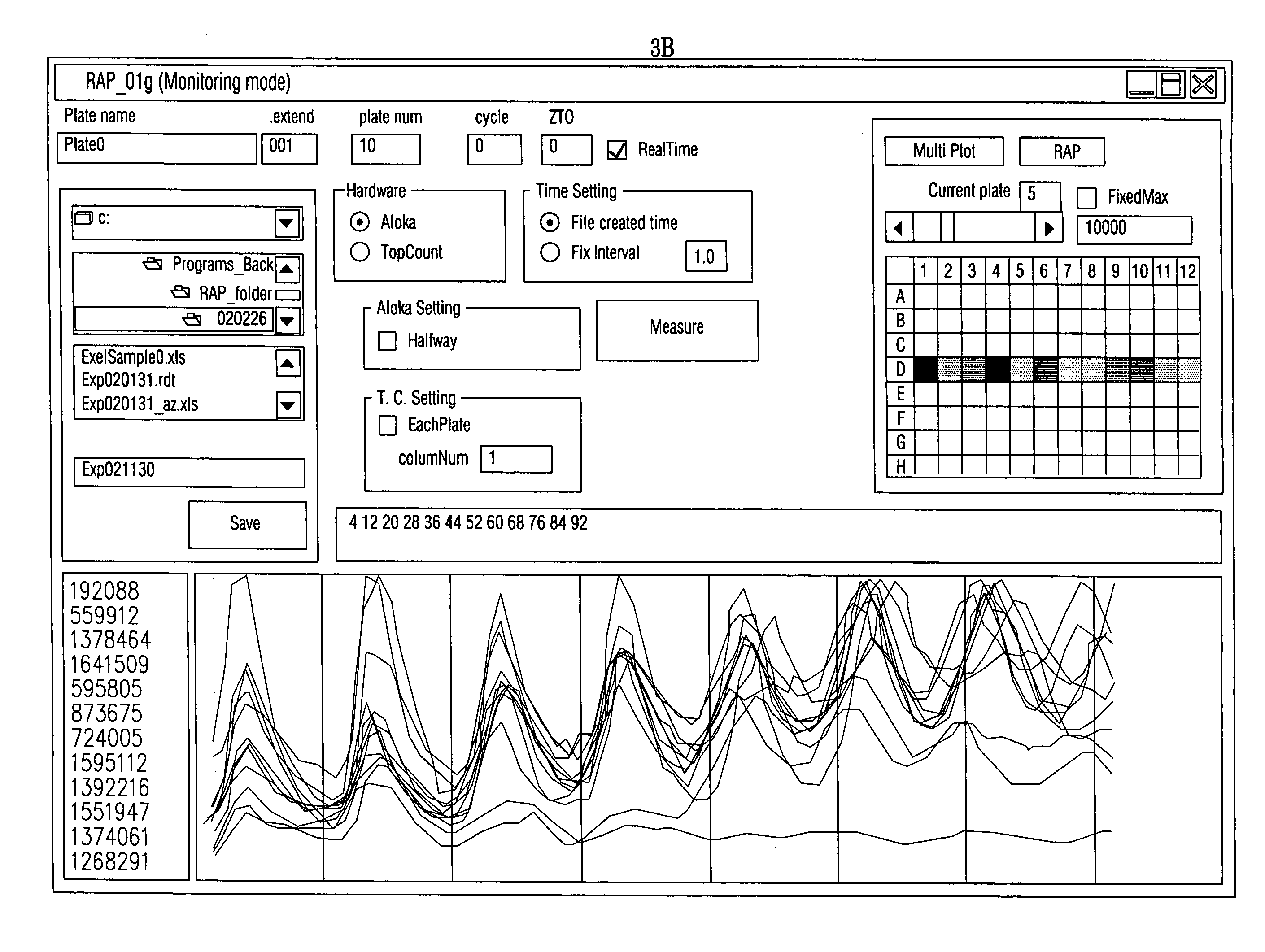
[0014]In the present invention, measurement data under bioluminescence measurement can be recognized in real-time by an operator, so that the measurement condition and the like can be controlled flexibly. For example, the measurement period of time can be shortened on the measurement data and another measurement preparation can be realized thereon. Therefore, the measurement efficiency in bioluminescence measurement can be raised.
[0041]According to the present invention, the measurement data can be analyzed precisely and easily, compared with a conventional technique as mentioned above. In the conventional technique, the measurement data are analyzed on MS-DOS program driven through Excel macro program, which inhibits the drive of another program during the analysis. In addition, some measurement data not required in analysis can not be removed. In the present invention, in contrast, analysis condition such as analysis period and analysis parameters can be controlled on the measurement results due to the real-time measurement and analysis.

Problems solved by technology

In a conventional measurement of bioluminescence, a tabular software program and an analysis software program for data processing can not be driven with a control software program of a bioluminescence measurement device simultaneously because the CPU is overloaded and OS (operation system) in the computer become to be unstable.
Therefore, the measurement results can not be recognized in real-time by an operator, so that the measurement condition and the like can not be controlled flexibly on the measurement results.
Moreover, since the conventional bioluminescence measurement apparatus does not contain any statistical processing functions, we can not analyze large-scaled measurement results rapidly and it requires much time in the judgment of the results (in this case, the measurement is stopped).
Particularly, it requires much time in the selection of mutants in a large-scaled genetic screening of mutant using bioluminescence.
Therefore, the bioluminescence measurement apparatus can not be utilized effectively.
With conventional bioluminescence measurement apparatus, however, a large-scaled measurement and analysis can not be realized.

Method used


Image

  • Method for measuring and analyzing bioluminescence and device for measuring and analyzing bioluminescence
  • Method for measuring and analyzing bioluminescence and device for measuring and analyzing bioluminescence
  • Method for measuring and analyzing bioluminescence and device for measuring and analyzing bioluminescence

Examples


example

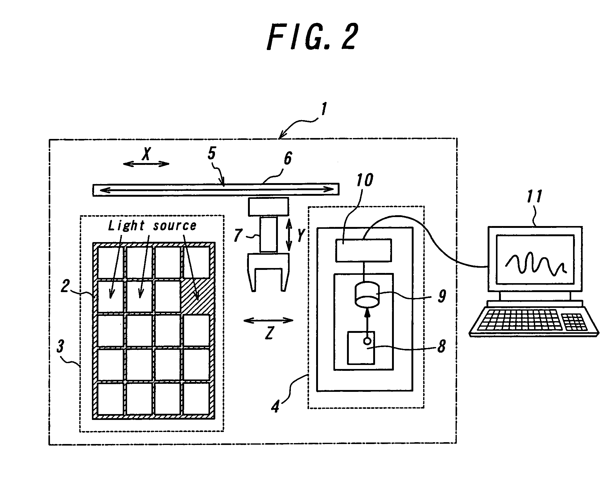
[0095]A plurality of plates, each with 96 wells, are prepared on the cultivating platform installed in the bioluminescence measuring apparatus, and measured per plate under cultivation. In this case, the plates are successively conveyed into the measurement unit. The luminescence from the samples in the plates are measured with the photon detector, and the thus obtained measurement results are transferred to the external computer. The measurement results are analyzed and displayed in real-time by the program in the present invention. After the measurement and analysis, the plates are brought back onto the cultivating platform. The above-mentioned process is repeated per measurement and analysis of one plate (FIG. 2).

[0096]According to the present invention, the measurement results can be displayed in real-time under measurement (FIG. 3B). On the real-time measurement, various measurement conditions can be flexibly set, and the measurement period of time can be shortened. Moreover, s...


PUM

PropertyMeasurementUnit
timeaaaaaaaaaa
bioluminescenceaaaaaaaaaa
luminescence measurementaaaaaaaaaa

Abstract

A method for measuring and analyzing bioluminescence, including the steps of receiving in real-time a luminescence measurement result group from a creature sample group, displaying and maintaining in real-time the luminescence measurement result group, receiving in real-time another luminescence measurement result group from the creature sample group, and displaying and maintaining in real-time the another luminescence measurement result group, instead of the luminescence measurement result group.

Description

BACKGROUND OF THE INVENTION[0001]1. Field of the Invention[0002]This invention relates to a method for measuring and analyzing bioluminescence and an apparatus for measuring and analyzing bioluminescence. This invention also contains a program for real-time monitoring and analyzing of bioluminescence data such as circadian bioluminescence rhythms. This invention is preferably useful in genetic screening of mutants for the research of gene expression, especially, research for the biological rhythms using bioluminescence reporter genes. Herein, the rhythm measurement and analysis is originated from that the biometry repeats one day periodic cycle with time within several days of measurement and analysis.[0003]2. Description of the Prior Art[0004]In a conventional measurement of bioluminescence, a tabular software program and an analysis software program for data processing can not be driven with a control software program of a bioluminescence measurement device simultaneously because ...

Claims


Application Information

Patent Timeline
Patent Type & Authority Patents(United States)
IPC IPC(8): A61B6/00G01N33/48G01N21/76G01N21/77
CPCG01N21/763
Inventor ISHIURA, MASAHIROOKAMOTO, KAZUHISA
Owner NAGOYA UNIVERSITY
Learn More