Acoustic signal level limiter

a limiter and acoustic signal technology, applied in the direction of transducer casings/cabinets/supports, substation equipment, electrical transducers, etc., can solve the problems of fixed resistor networks that cannot adjust the amount of attenuation of electrical signals, and the transistors within the acoustic signal level relay circuit may be deeply saturated

Active Publication Date: 2007-04-03
PLANTRONICS
View PDF5 Cites 14 Cited by
  • Summary
  • Abstract
  • Description
  • Claims
  • Application Information

AI Technical Summary

Benefits of technology

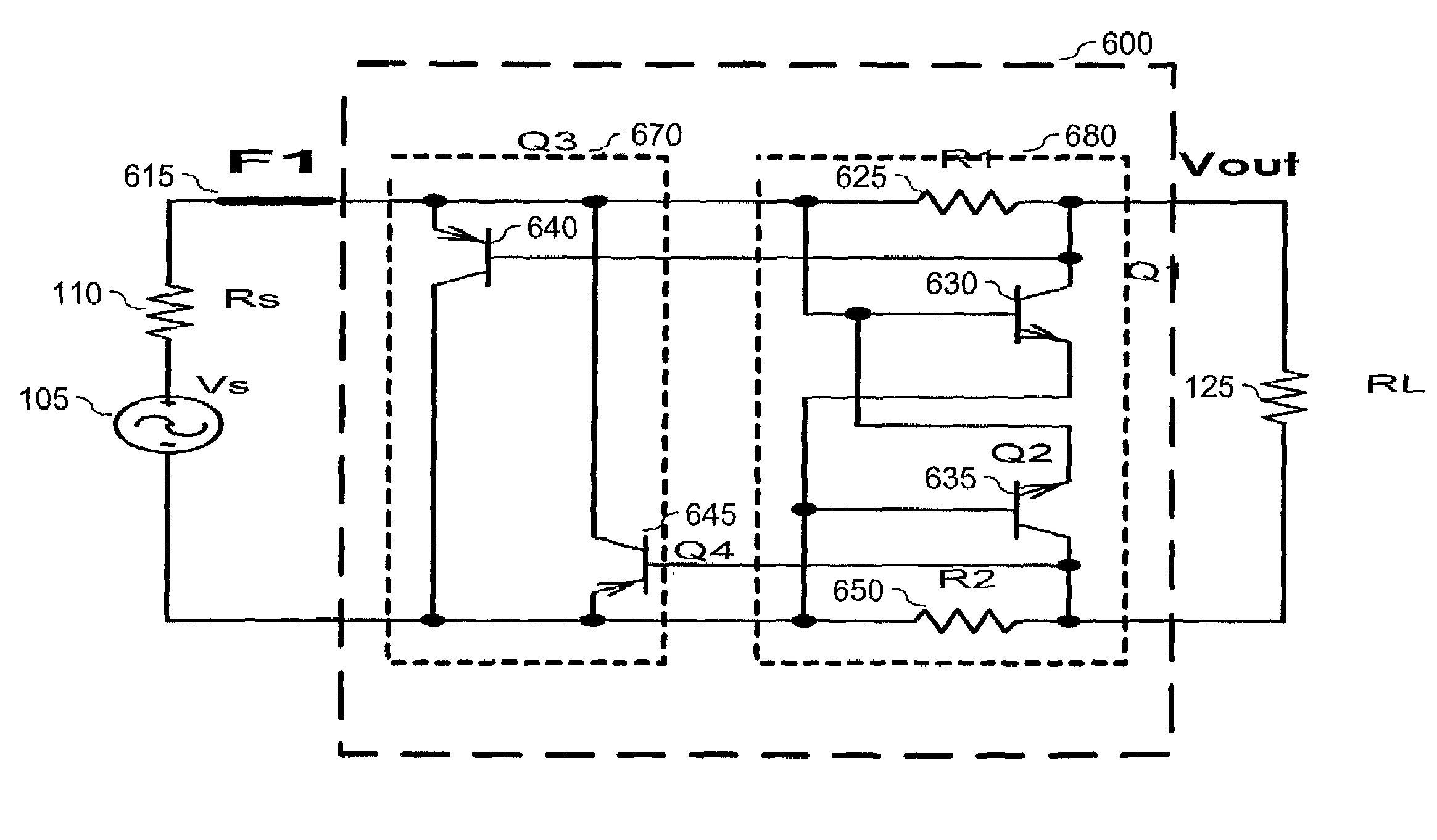
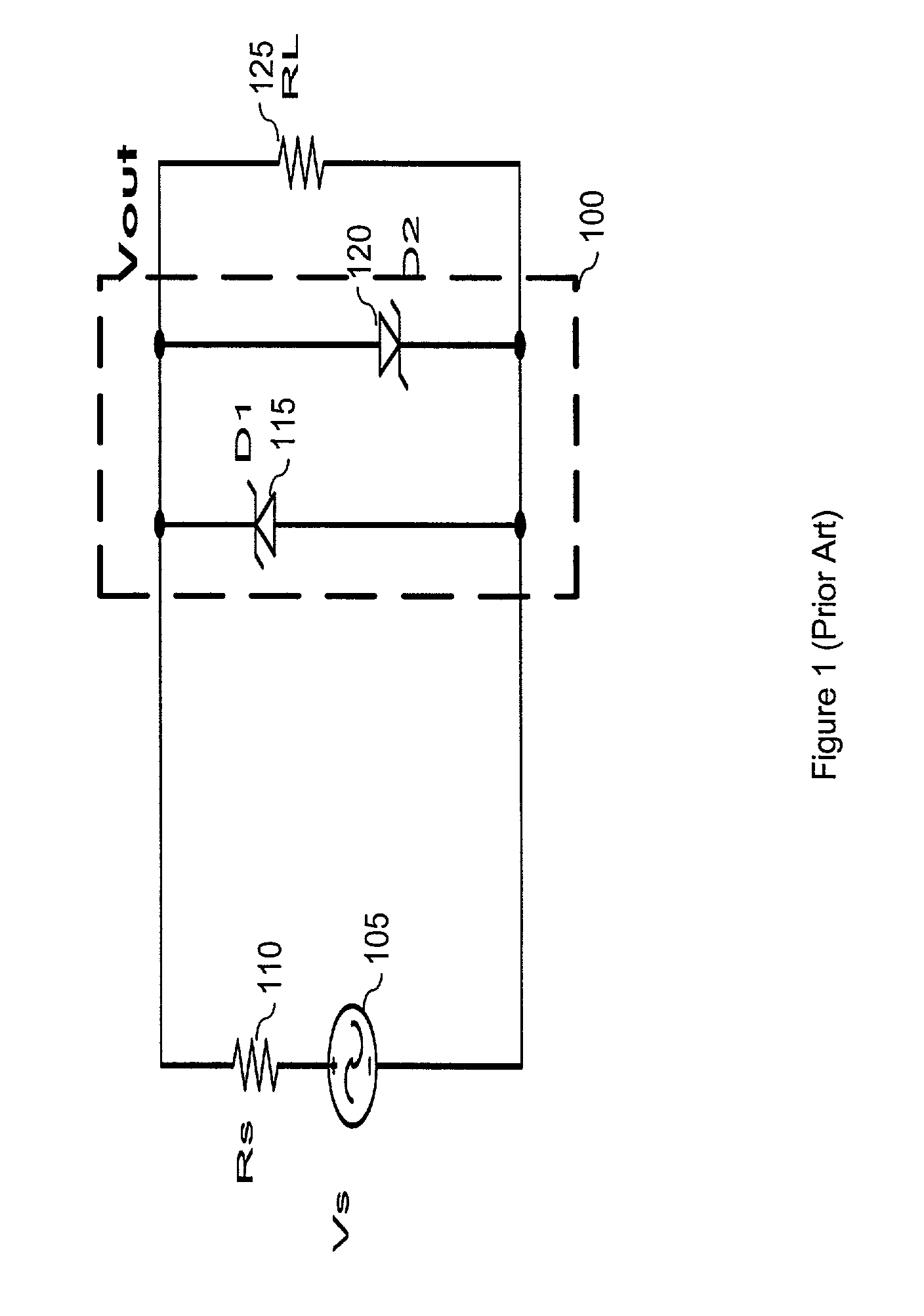
[0017]The present invention overcomes the deficiencies and limitations of the prior art by providing a hearing safety system and method that limits an acoustic signal level to a predetermined threshold. In one embodiment, an acoustic signal level limiter circuit is coupled between a voltage source and a load. Within the field of telecommunications, the voltage source may be a telephone or telephone adapter, and the load may be a telephone handset or headset. The acoustic signal level limiter circuit limits electrical signal levels from the voltage source by implementing multiple attenuation networks that are activated as the electrical signal crosses voltage levels. If the electrical signal level is sufficiently high to activate at least one of these attenuation networks, then the electrical signal is attenuated accordingly. As a result of this signal attenuation, the acoustic signal level limiter circuit is able to maintain a maximum signal level threshold through which the electrical signal is prevented from crossing. Ultimately, when the signal level is high enough to exhaust the attenuation potential of the limiter, a combination series fuse and / or shunt short disconnects all output to the load. This maximum signal level threshold protects a user of a communication device (e.g., a telephone headset) from signals that could produce undesirable audio levels.
[0018]The acoustic signal level limiter comprises an acoustic signal level attenuation circuit and at least one acoustic signal level relay circuit. The acoustic signal level limiter may be designed to handle various levels of signal overload by adjusting the number of acoustic signal level relay circuits. As the number of acoustic signal level relay circuits integrated within the acoustic signal level limiter increases, the ability of the acoustic signal level limiter is enhanced to protect against extremely high electrical signal levels within the communication system. Thus, the acoustic signal level limiter can be flexibly designed by increasing or decreasing the number of relays to handle different levels of signal overload. Finally, the series fuse and / or shunt short mechanism will disconnect output signals to the speaker load.
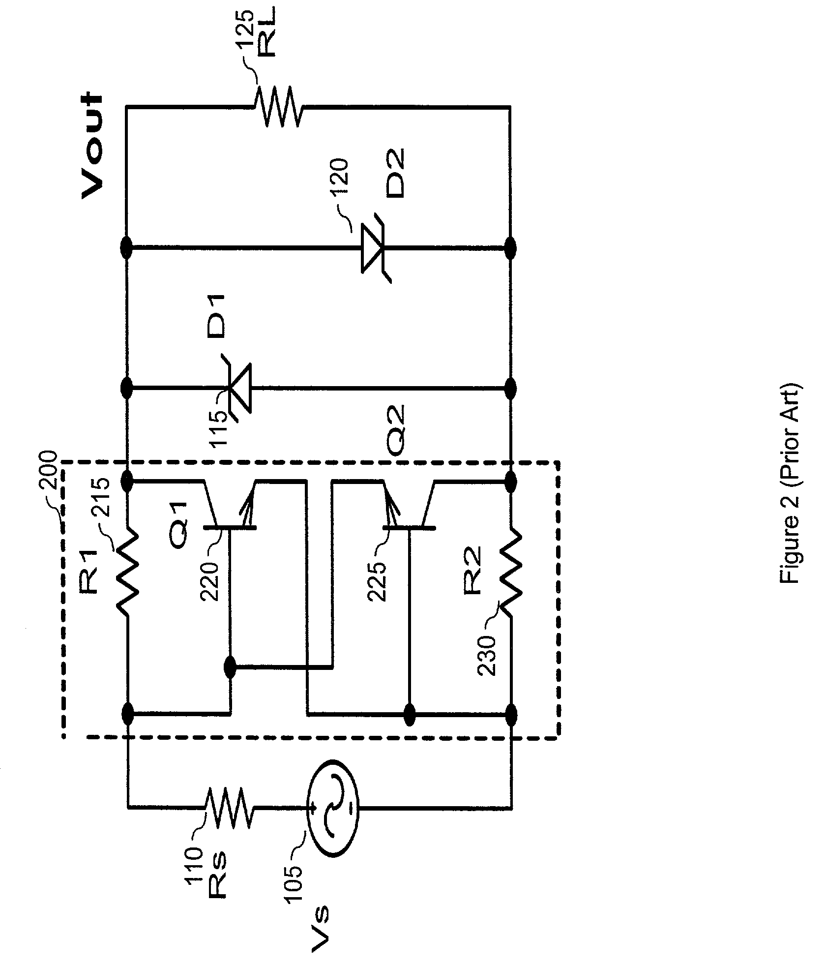
[0020]An acoustic signal level relay circuit is integrated within the acoustic signal level limiter to enhance the operation of the acoustic signal level attenuation circuit. The acoustic signal level relay circuit inhibits the acoustic signal level attenuation circuit from entering a deep saturation mode. Specifically, once activated, the acoustic signal level relay circuit further attenuates the electrical signal from the voltage source in order to prevent the electrical signal from deeply saturating the transistors within acoustic signal level attenuation circuit and further reduce the voltage level across the load. However, like the transistors in the acoustic signal level attenuation circuit, the transistors within the acoustic signal level relay circuit may be deeply saturated if the electrical signal level is sufficiently high. The integration of the acoustic signal level relay circuit increases the required level at the voltage source to saturate the acoustic signal level attenuation circuit due to the fact that it is further attenuating the electrical signal from the voltage source.
[0021]Additional acoustic signal level relay circuits may be integrated within the acoustic signal level limiter in order to further increase the required level at the voltage source to saturate the acoustic signal level attenuation circuit. As a result, a manufacturer may design the acoustic signal level limiter according to the environment in which it operates and the particular needs of the user. For example, a telephone communications headset may require only a certain number of acoustic signal level relay circuits in order to protect against large signals propagating through a telephone line. At signal levels well beyond what is to be expected in an application, the series fuse / shunt short mechanism of the invention provides the ultimate fail safe, disabling the headset speaker drive. In addition to establishing a maximum electrical signal level threshold, the acoustic signal level limiter offers other performance advantages over current devices that are being implemented.
[0022]The acoustic signal level limiter takes advantage of specific characteristics of transistors within the acoustic signal level attenuation circuit and the acoustic signal level relay circuit(s) to provide enhanced signal level clamping effects. For example, the transistor network introduces less distortion than the varistor on the electrical signal as the electrical signal voltage level approaches the turn-on voltage. Also, the transistor circuits, rather than providing a simple flat topped clipping of the diodes, generate a concave topped waveform containing less energy.
[0023]The characteristics of the transistors may be modified by using various types of transistors (e.g. bipolar junction transistors (BJTs) or field effect transistors (FETs)). For instance, junction field effect transistors (JFETs) may be implemented to designate different pinch-off voltages, and correspondingly, manipulate the maximum signal level threshold allowed across the load. Additionally, the acoustic signal level limiter may be fabricated to provide a Zener diode effect on specific transistors. This Zener diode effect or “Zener Zap” is an integrated bipolar technology effect that provides a fuse that will trigger if a particular current level is reached within the circuit. Thus, a “Zener Zap” or other fuse device may be provided to isolate the load from the voltage source in the event the electrical signal level is too high for the acoustic signal level limiter to effectively attenuate the electrical signal.

Problems solved by technology

However, the transistors within the acoustic signal level attenuation circuit will operate in a deep saturation mode if the electrical signal level is too high.
Deeply saturated transistors are unable to effectively attenuate the electrical signal resulting in the attenuation network, in which the transistors operate, to function similar to a resistor network.
Specifically, the effective resistance of transistors in deep saturation is constant resulting in a fixed resistor network that cannot adjust the amount of attenuation on the electrical signal.
However, like the transistors in the acoustic signal level attenuation circuit, the transistors within the acoustic signal level relay circuit may be deeply saturated if the electrical signal level is sufficiently high.

Method used


Image

  • Acoustic signal level limiter
  • Acoustic signal level limiter
  • Acoustic signal level limiter

Examples


Embodiment Construction

[0034]In the following description, for purposes of explanation, numerous specific details are set forth in order to provide a thorough understanding of the invention. It will be apparent, however, to one skilled in the art that the invention can be practiced without these specific details. In other instances, structure and devices are shown in block diagram form in order to avoid obscuring the invention. Moreover, it should be noted that the language used in this disclosure has been principally selected for readability and instructional purposes, and may not have been selected to delineate or circumscribe the inventive subject matter, resort to the claims being necessary to determine such inventive subject matter.

[0035]A. System Overview

[0036]The present invention limits the level of an incoming electrical acoustic signal to a particular maximum threshold. FIG. 4 is a general block diagram showing an embodiment of the present invention. As shown, this embodiment operates between a ...


PUM


Abstract

An acoustic signal level limiter provides a telephone handset / headset user protection against loud audible signals generated within a communications system. The acoustic signal limiter comprises an acoustic signal level attenuation circuit and at least one acoustic signal level relay circuit. Once activated, the acoustic signal level attenuation circuit creates an attenuation network that attenuates an electrical acoustic signal transmitted through the communications system. Acoustic signal level relay circuits are activated to further attenuate the electrical acoustical signal to prevent the acoustic signal level attenuation circuit from operating in a deep saturation mode and provide further hearing safety for the telephone headset / handset user. A fuse in series and “Zener Zap” shunting transistor diodes provide assured higher signal level protection.

Description

BACKGROUND[0001]A. Technical Field[0002]The present invention relates generally to acoustic signal level detection and control, and more particularly, to hearing safety protection in communication devices by limiting the level of an acoustic signal that will be transmitted to a listener through a communication device.[0003]B. Background of the Invention[0004]Proper control of electrical acoustic signal levels within a communication system is desirable in order to ensure high quality communication and hearing safety to individuals using the system. Generally, a telephone handset or headset includes a microphone and a speaker. For example, a telephone headset provides a microphone on an arm that is positioned proximately to a user's mouth and a speaker within an earpiece that is positioned over the user's ear. In order to provide proper communication, the sound level of the audible signal emitted from the speaker should fall within a range of sound intensity. If the sound level is bel...

Claims


Application Information

Patent Timeline
Patent Type & Authority Patents(United States)
IPC IPC(8): H04B15/00
CPCH04M1/6058
Inventor SHYU, CHINGKHAMASHTA, ROBERTBERNARDI, ROBERT J.
Owner PLANTRONICS
Why Eureka
Try Eureka