Vapor-lift pump heat transport apparatus

a heat transport apparatus and vapor lift technology, which is applied in the direction of indirect heat exchangers, geothermal energy generation, lighting and heating apparatus, etc., can solve the problems of difficult downward heat transport, limited heat transport directions of thermosyphons, and small heat transport capacity, and achieve large heat transport capacity, small heat resistance, and high reliability

Active Publication Date: 2007-04-10
MITSUBISHI ELECTRIC CORP
View PDF11 Cites 27 Cited by
  • Summary
  • Abstract
  • Description
  • Claims
  • Application Information

AI Technical Summary

Benefits of technology

[0008]An object of the present invention is to solve the above problems and thereby provide an vapor-lift pump type heat transport apparatus having a small heat resistance and a large heat transport capacity. Another object of the invention is to provide a highly reliable vapor-lift pump type heat transport apparatus in which the circulation flow rate of a circulating solution does not tend to ripple.
[0010]In this vapor-lift pump type heat transport apparatus, the positions of the vapor-liquid interfaces in the two spaces vary passively in accordance with the magnitude of the heat load, whereby pressure increase in the apparatus can be suppressed. This provides an advantage that a heat transport apparatus having a large heat transport capacity can be obtained. A large amount of heat can be transported even with a small temperature difference. Further, the conditions relating to the withstand pressure design can be relaxed and hence the weight of the apparatus can be reduced.
[0012]This configuration makes it possible to provide an vapor-lift pump type heat transport apparatus having a small heat resistance and a large heat transport capacity.
[0014]This configuration makes it possible to provide an vapor-lift pump type heat transport apparatus having a small heat resistance and a large heat transport capacity.

Problems solved by technology

However, thermosyphons are limited in heat transport directions; in particular, it is difficult to perform downward heat transport.
However, the conventional heat transport apparatus has problems that a maximum heat transport capacity is small, the heat resistance is large (i.e., the heat characteristics are poor), and heat transport is difficult with a small temperature difference.
Another problem is that when the heat load is light the circulation flow rate of the heat exchange circulating solution that circulates through the circulating solution transport pipe is intermittent to and causes vibration.

Method used


Image

  • Vapor-lift pump heat transport apparatus
  • Vapor-lift pump heat transport apparatus
  • Vapor-lift pump heat transport apparatus

Examples


embodiment 1

[0054]The above-described conventional heat transport apparatus has such problems as a small maximum heat transport capacity and a large heat resistance. However, the present invention has been made by revealing that these problems are caused by a pressure increase in the container.

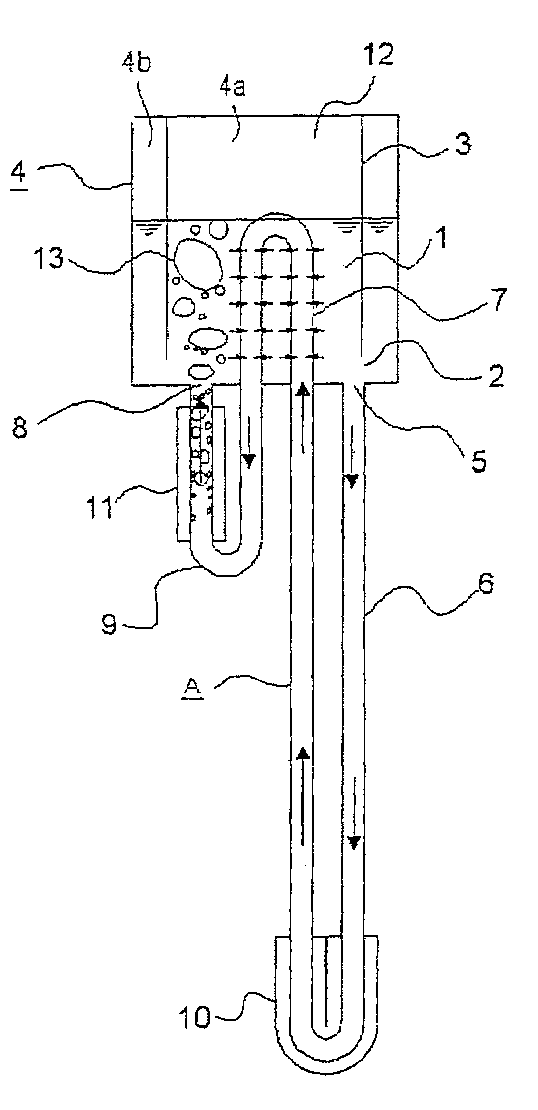
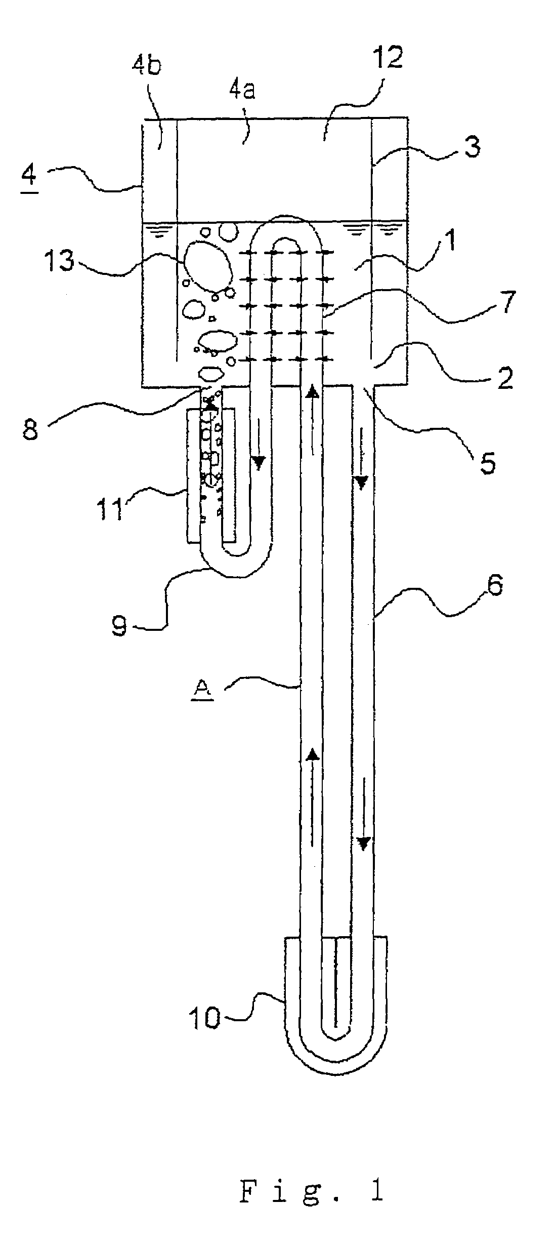
[0055]As the heat load increases, a large amount of vapor bubbles generated in the heating heat exchanger comes to flow into the heat exchange circulating solution container. Since the heat exchange capability of the outer surface of the intra-container pipe is small, the vapor bubbles cannot condense sufficiently and hence the pressure inside the apparatus increases. As a result, the saturation temperature inside the apparatus increases and the difference between the temperatures inside and outside the intra-container pipe becomes large. Since the temperature difference between the heating heat exchanger and the sensible heat releasing heat exchanger increases, the heat resistance of the apparatus is muc...

embodiment 2

[0082]FIG. 5 is a sectional view showing the configuration of an vapor-lift pump type heat transport apparatus according to a second embodiment of the invention. In the embodiments of the invention, the same components or components corresponding to each other are given the same reference symbol. As shown in FIG. 5, as in the first embodiment, the heat exchange circulating solution container 4 is divided by the partition 3 into the first space 4a and the second space 4b. However, in the second embodiment, the first space 4a is the outside space and the intra-container pipe 7 is provided spirally in the first space 4a so as to surround the inside second space 4b. Even with this configuration, the same advantages as in the first embodiment can be provided.

[0083]FIG. 6 is a sectional view showing the configuration of another vapor-lift pump type heat transport apparatus according to the second embodiment. As shown in FIG. 6, the heat exchange circulating solution container 4 is divided...

embodiment 3

[0085]FIG. 7 is a sectional view showing the configuration of an vapor-lift pump type heat transport apparatus according to a third embodiment of the invention. FIG. 8 is a sectional view showing the configuration of another vapor-lift pump type heat transport apparatus according to the third embodiment. As shown in FIGS. 7 and 8, this apparatus is not such that the internal space of the heat exchange circulating solution container 4 is divided by the partition 3. Instead, a second heat exchange circulating solution container 4d is provided outside a first heat exchange circulating solution container 4c and connected to the container 4c. The first heat exchange circulating solution container 4c and the second heat exchange circulating solution container 4d perform functions corresponding to the functions of the first space 4a and the second space 4b of the first embodiment, respectively.

[0086]As for the location of the second heat exchange circulating solution container 4d, the only...


PUM


Abstract

A vapor-lift pump heat transport apparatus having a small heat resistance and a large heat transport capacity. A heat exchange circulating solution container has a first space and a second space communicating with the first space through a communication opening and contains a heat exchange circulating solution, and vapor thereof, in each space. A circulating solution transport passage includes a pipe connected to the solution outlet of the container and provided with a sensible heat releasing heat exchanger, a pipe disposed in the container, and a pipe connected to a vapor-liquid two-phase fluid inlet and provided with a heating heat exchanger. A vapor-liquid two-phase fluid flows into only the first space through the vapor-liquid two-phase fluid inlet. When the entrance of the vapor-liquid two-phase fluid has caused a pressure difference between the first and second spaces, a difference occurs between the positions of the vapor-liquid interfaces in the first and second spaces.

Description

BACKGROUND OF THE INVENTION[0001]1. Field of the Invention[0002]The present invention relates to a heat transport apparatus. In particular, the invention relates to an vapor-lift pump (bubble pump) heat transport apparatus that uses an vapor-lift pump and requires no external motive power.[0003]2. Description of the Related Art[0004]Conventionally, thermosyphons (i.e., heat pipes using gravity) are used as heat transport apparatus that use no external motive power. However, thermosyphons are limited in heat transport directions; in particular, it is difficult to perform downward heat transport. In these circumstances, a heat transport apparatus using an vapor-lift pump has been developed as a new heat transport apparatus (refer to JP-A-2002-122392, for example). As shown in FIG. 1 of JP-A-2002-122392, this heat transport apparatus is equipped with a heat exchange circulating solution container for containing a heat exchange circulating solution whose temperature is increased to a hi...

Claims


Application Information

Patent Timeline
Patent Type & Authority Patents(United States)
IPC IPC(8): F28D15/00F28D7/04F28D15/02
CPCF24J3/081F24J3/086F28D15/0266F28D20/0052Y02E10/12Y02E10/16Y02E60/142F28F2250/08F24T10/10F24T10/30F24T10/40Y02E10/10Y02E60/14
Inventor IPPOUSHI, SHIGETOSHIUEHARA, NOBUAKIYAMADA, AKIRAOGUSHI, TETSUROYAMAKAGE, HISAAKI
Owner MITSUBISHI ELECTRIC CORP
Why Eureka
Try Eureka