Wafer boat for consolidation of porous thin layer

Active Publication Date: 2007-04-10
SAMSUNG ELECTRONICS CO LTD
View PDF5 Cites 16 Cited by
  • Summary
  • Abstract
  • Description
  • Claims
  • Application Information

AI Technical Summary

Benefits of technology

[0014]One aspect of the present invention is to provide a wafer boat with a structure that prevents particles from a porous oxide layer of a wafer from falling down to another oxide layer of another wafer located underneath.
[0015]Another aspect of the present invention is to provide a wafer boat in which it is possible to obviate the need to enlarge the consolidation furnace and to facilitate a wafer automation system.
[0016]Another aspect of the present invention is to provide a wafer boat in which it is possible to prevent a porous oxide layer of a wafer from being damaged due to contact with other structures, such as support rods, by limiting movement of the wafer mounted to the wafer boat.

Problems solved by technology

In this state, the thin layer protruding out of the substrate edge is extremely vulnerable to breakage even by the slightest impact, resulting in the broken particles falling down onto another wafer mounted underneath, which in turn causes other defects in the products.
However, the surface of the dummy wafer will be oxidized leading to crystallization because the consolidation process is performed at a high temperature of about 1300° C. Fine crystals formed on the surface of the dummy wafer will fall down to another wafer located underneath, causing the defects in the oxide layer on the wafer.
However, such a solution increases production costs.
Also, in a case in which the mounting of the substrate is automated, a complicated wafer automation system is required so as to make use of the dummy wafer, and the operation of the automation system also will be complicated.

Method used


Image

  • Wafer boat for consolidation of porous thin layer
  • Wafer boat for consolidation of porous thin layer
  • Wafer boat for consolidation of porous thin layer

Examples


Embodiment Construction

[0029]Hereinafter, a preferred embodiment of the present invention will be described with reference to the accompanying drawings. For the purposes of clarity and simplicity, the same reference numerals are used to designate the same or similar components, and so repetition of the description on the same or similar components will be omitted.

[0030]FIG. 4 is a side view of a wafer boat 400 for consolidation of a porous oxide layer according to a preferred embodiment of the present invention. FIG. 5 is a cross-sectional top view of the wafer boat 400 taken along a line B–B′ of FIG. 4. FIG. 6 is a perspective view of a support plate 420 shown in FIG. 4. FIG. 7 is a cross-sectional side view of the wafer boat 400 taken along a line C–C′ of FIG. 5.

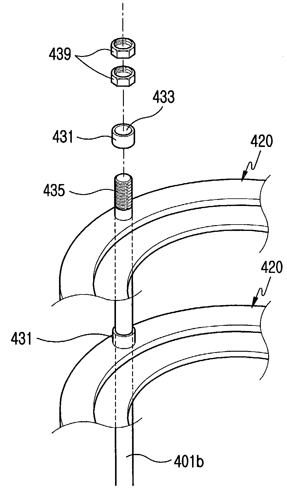
[0031]As shown in FIGS. 4 to 7, the wafer boat 400 according to the preferred embodiment of the present invention includes an upper plate 405, a lower plate 407, three support rods 401 and a plurality of support plates 420.

[0032]Each of the sup...


PUM


Abstract

A wafer boat for consolidation of a porous oxide layer structure is provided. The wafer boat includes at least one support plate including: a first plate for supporting a substrate with the porous oxide layer by face-to-face contact; a second plate radially extending from a periphery of the first plate; and a stepped portion for limiting movement of the substrate formed with a predetermined height along a border line between the first plate and the second plate. The wafer boat also includes a support plate supporting the edge of the wafer to be consolidated, so that it is possible to prevent the porous layer of a wafer located underneath from being damaged by the falling particles from the broken particles from the porous layer of the wafer located at the upper side. Also, the omission of a dummy wafer can reduce the size of the consolidation furnace, and the automation system and the process can be simplified leading to reduction of the production cost. In addition, since a stepped portion is provided for limiting movement of the wafer mounted on the wafer boat, damage to the porous layer of the wafer due to contact of the wafer with the support rod can be prevented.

Description

CLAIM OF PRIORITY[0001]This application claims priority to an application entitled “Wafer boat for consolidation of porous thin layer,” filed in the Korean Intellectual Property Office on Dec. 12, 2002 and assigned Serial No. 2002-79112, the contents of which are hereby incorporated by reference.BACKGROUND OF THE INVENTION[0002]1. Field of the invention[0003]The present invention relates to a device for fabricating a thin layer on a silicon wafer. More particularly, the present invention relates to a wafer boat for use in a consolidation process after a deposition of silica layer.[0004]2. Description of the Related Art[0005]In the prior art, oxide layers for the fabrication of a planar light-wave circuit are produced through a flame hydrolysis deposition process. The flame hydrolysis deposition includes deposition of oxide particles, such as SiO2, GeO2, P2O5, or B2O3 onto a silicon substrate or a quartz substrate, and then a subsequent consolidation process. In the process of the fl...

Claims


Application Information

Patent Timeline
IPC IPC(8): A47G19/08H01L21/22H01L21/673
CPCH01L21/67309H01L21/22
Inventor CHO, JAE-GEOL
Owner SAMSUNG ELECTRONICS CO LTD
Why Eureka
Try Eureka