Swashplate seal assembly

a technology of seal assembly and rotor bearing, which is applied in the direction of rotors, vessel construction, marine propulsion, etc., can solve the problems of rotor bearing ring water seeping down the rotor shaft to bearing and associated components that are not worn normally, and parts that are not easily damaged, so as to reduce the frequency of inspection, improve the protection of the rotor bearing ring bearing, and maximize the effect of operation

Inactive Publication Date: 2007-04-10
US ARMY SEC OF THE GOVERNMENT OF THE UNITED STATES AS REPRESENTED BY THE +1
View PDF6 Cites 7 Cited by
  • Summary
  • Abstract
  • Description
  • Claims
  • Application Information

AI Technical Summary

Benefits of technology

[0009]A swashplate seal assembly is disclosed for protection of a rotor bearing unit as utilized in-the aviation industry for helicopter rotor units. The seal assembly is positioned outboard of one or more rotor bearing rings encircling a rotor shaft. The seal assembly provides improved protection of rotor bearing ring bearings from exposure to moisture and environmental contaminants to maximize operation during flight, to reduce frequency of inspections for rotor bearing and seals, and to reduce the time of each inspection for rotor bearings, seals and associated rotating parts utilized in rotor shaft units. The swashplate seal assembly includes an outer segmented cover encircling the rotor shaft. The outer segmented cover is positioned to cover a sealing ring including an inner circumference on which one or more resilient sealing members are inwardly disposed. The outer segmented cover, sealing ring and resilient sealing members are sectioned into a multitude of respective like-configured curved segments for ease of disassembly without removal of all curved segments during rotor shaft inspections. A flanged seal ring is positonable inboard of the sealing ring and includes an outer surface having an outer diameter sufficiently limited to allow the seal ring to be positioned within, and preferably in sliding contact with, the resilient sealing members. The seal ring is fitted on an outer perimeter of a bearing retainer sized to be positioned within the sealing ring to slidingly engage the seal ring outer surface within the resilient sealing members during rotor shaft rotation. The outer cover positioning and the engaging relationship between the seal ring and sealing ring resilient sealing members operate to minimize contaminants intrusion along a length of the rotor shaft and in rotor bearing ring(s) encircling the rotor shaft. A process of assembly and disassembly is also disclosed herein for the swashplate seal assembly.

Problems solved by technology

A large number of maintenance issues arise in the swashplate assembly and the rotor bearing ring assembly due to wear in all parts, binding of seals, metal fatigue in the rotor bearing ring, and bearing spalling leading to abnormal wear of bearings and associated components.
Frequent cleaning of a rotor shaft assembly outer surfaces and shaft seals leads to water seeping down the rotor shaft to the rotor bearing ring if a swashplate seal assembly is in a state of degradation due to exposure to contaminants and / or frequent disassembly during inspections of the rotor bearing ring.
Due to the logistics of operating a helicopter for military use, any potential failure of parts as indicated by inspection findings and partial failures is consider highly significant due to a risk of loss of life when helicopter seal assemblies fail.
During the prior decade of helicopter operations, a significant number of problems relating to helicopter swashplate assemblies have occurred due to stress fractures in rotor bearing cages and / or bearing components contact leading to abnormal bearing component wear which leads to catastrophic results.
In order to prevent catastrophic results, frequent and extensive rotor shaft, rotor bearing cage, and swashplate seal assembly inspections are accomplished, with resulting loss of helicopter flight time.

Method used


Image

  • Swashplate seal assembly
  • Swashplate seal assembly
  • Swashplate seal assembly

Examples


Embodiment Construction

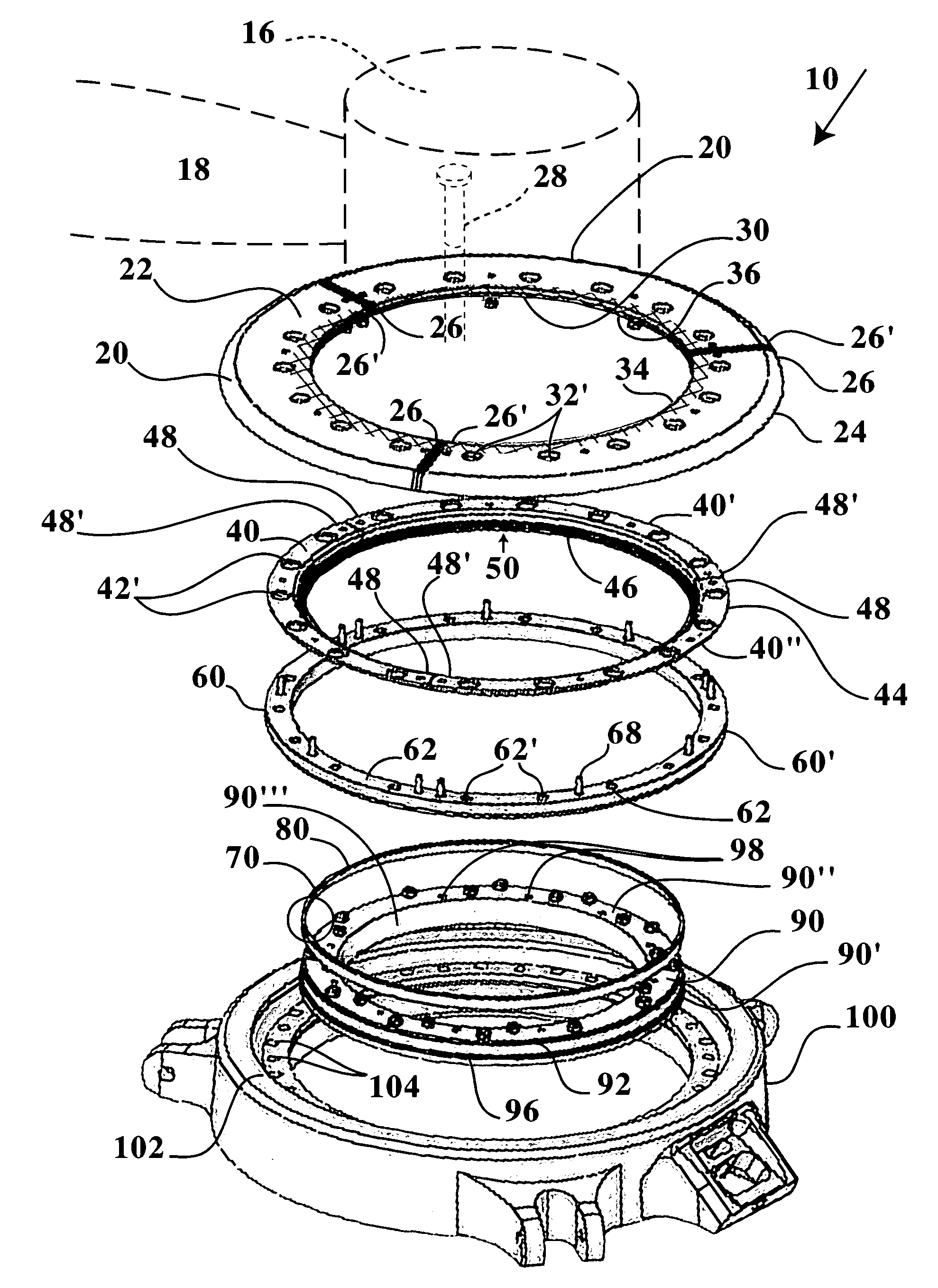
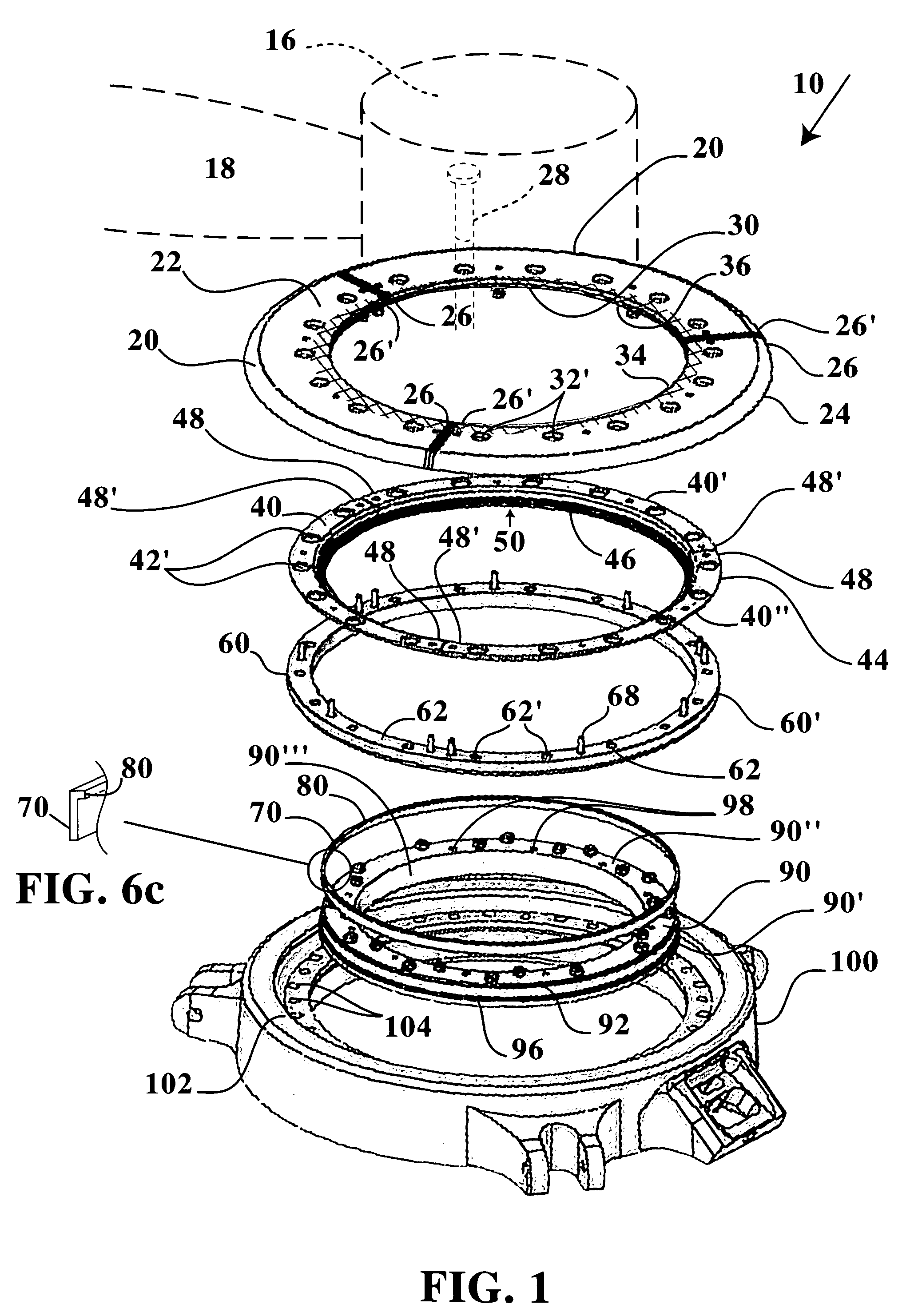
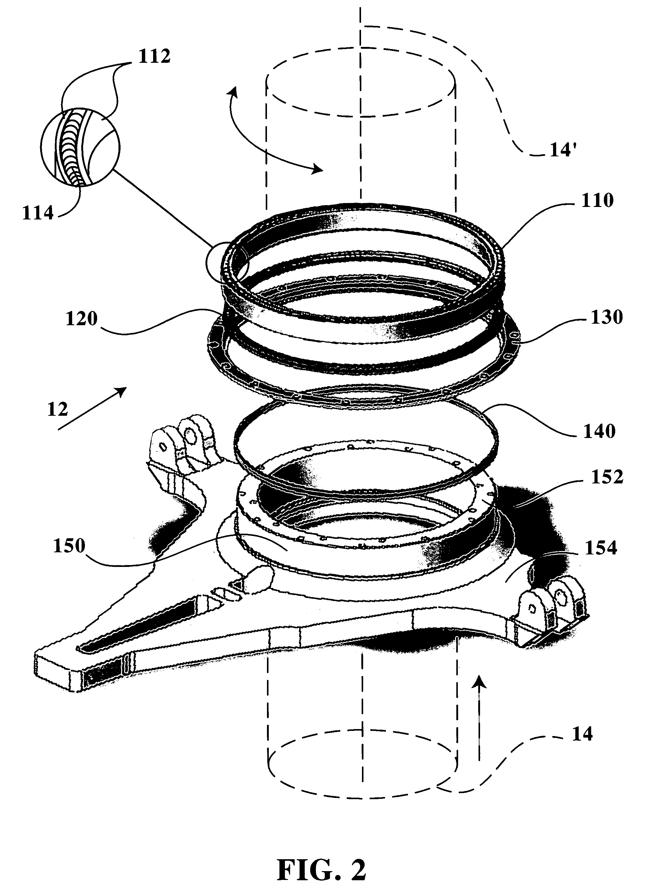
[0018]Referring to FIGS. 1 through 7, a swashplate seal assembly 10 is disclosed through which a rotor shaft 14 is rotatable as is typical of a helicopter rotor unit extending from a transmission coupled to an engine unit. The rotor shaft 14 extends along its rotational axis 14′ to a distal blade rotor hub 16 on which a plurality of helicopter blades 18, 18′, 18″ extend. The swashplate seal assembly 10 is stacked in coaxial orientation around the rotational axis 14′, with the seal assembly 10 being positioned to rotate within a rotor ring unit 100 which is releasably attachable to a rotor hub assembly 12 composed of a rotor base ring 150, through which a rotor shaft 14 extends to a distal blade rotor hub 16 from which a plurality of helicopter blades 18 radially extend. The stacked, interlocking alignment, and cooperative function of the multiple layers of the swashplate seal assembly 10 provide for improved protection of a helicopter rotor bearing ring unit 110 from excessive beari...


PUM


Abstract

A swashplate seal assembly sized for rotor shaft rotation therein, including an outer cover encircling the rotor shaft and covering a sealing ring having an inner circumference on which a resilient sealing wiper is inwardly disposed. The outer cover, sealing ring and resilient sealing wiper are sectioned in respective like-configured curved segments for disassembly without removing adjacent segments during inspections. Inboard of the sealing ring is a flanged seal ring having an outer surface diameter limited in size to allow positioning the seal ring within the sealing wiper. The seal ring is fitted on an outer perimeter of a bearing retainer positionable within the sealing ring, thereby positioning the seal ring outer surface in sliding engagement with the sealing wiper during rotor shaft rotation. The outer cover positioning and the engaging relationship between seal ring and sealing wiper operate to minimize contaminants intrusion along the rotor shaft during rotation.

Description

STATEMENT REGARDING FEDERALLY SPONSORED RESEARCH OR DEVELOPMENT[0001]The invention described herein may be manufactured, used and licensed by or for the Government for governmental purposes without the payment to the inventors and / or the assignee of any royalties thereon.CROSS-REFERENCE TO RELATED APPLICATIONS[0002]Not Applicable.BACKGROUND OF THE INVENTION[0003]1. Field of the Invention[0004]The invention relates to a seal assembly for aviation rotor bearings. More specifically, the invention relates to a swashplate seal assembly for protection of rotorcraft bearings associated with a rotor shaft unit.[0005]2. Description of the Related Art[0006]Conventional rotorcrafts such as helicopters and tilt wing aircraft having propulsion systems which are adjustable in positioning angle, typically include rotor shaft units having one or more rotor bearing ring assembles which are accompanied by swashplate assemblies. Examples of conventional helicopter swashplate assemblies are provided in...

Claims


Application Information

Patent Timeline
Patent Type & Authority Patents(United States)
IPC IPC(8): F04D29/10
CPCB64C27/605F16J15/3272
Inventor PARSONS, WAYNE C.CONKLIN, TRACY A.
Owner US ARMY SEC OF THE GOVERNMENT OF THE UNITED STATES AS REPRESENTED BY THE
Why Eureka
Try Eureka