Method for characterizing a subsurface formation with a logging instrument disposed in a borehole penetrating the formation

a technology of logging instrument and subsurface formation, which is applied in the field of well logging, can solve the problems of affecting image quality, the quality of the image does not permit accurate dip determination, and the work of the electrode tool, so as to achieve the effect of quite high accuracy of dip determination

Active Publication Date: 2007-04-10
SCHLUMBERGER TECH CORP
View PDF28 Cites 87 Cited by
  • Summary
  • Abstract
  • Description
  • Claims
  • Application Information

AI Technical Summary

Benefits of technology

[0029]In one aspect, the present invention provides a method and apparatus to determine the dip and strike of an earth formation based on directional (i.e., azimuthal) measurements. The measurements are relatively deep so the effects of the borehole environment, compared with conventional borehole imagers, are much less significant. Another advantage is that the invention works in both conductive and resistive mud. The accuracy of the dip determination can be quite high, especially when the relative dip is not close to 90°.
[0039]3. less borehole-environment dependence, and freedom of borehole mud cake and mud / filtrate effects;

Problems solved by technology

Furthermore, the FMI tool and other electrode tools work only in conductive mud.
Analysis of the obtained real-time image at the surface can remove this restriction, but since the image is acquired using one-inch electrode buttons, the quality of the image does not permit accurate determination of dip when relative dip is low.
The fast rate of penetration can also affect the image quality and thus dip accuracy from the image.
The quality of the image is poorer than that of the FMI tool, and the error on determined dips will be larger than that of the FMI tool.
Currently, no electric image tools provide dip services in both conductive and insulating mud.
This is not, however, an accurate depiction of all the numerous segments that make up a borehole—particularly when the borehole has been directionally-drilled as described below.
However, such tools are inherently non-directional and, therefore, are incapable of providing azimuthal information about the bedding structure.
Thus, commercially available wireline induction and LWD propagation resistivity tools are presently unable to accurately determine dip.
These applications are limited to formations with anisotropy.

Method used


Image

  • Method for characterizing a subsurface formation with a logging instrument disposed in a borehole penetrating the formation
  • Method for characterizing a subsurface formation with a logging instrument disposed in a borehole penetrating the formation
  • Method for characterizing a subsurface formation with a logging instrument disposed in a borehole penetrating the formation

Examples


Embodiment Construction

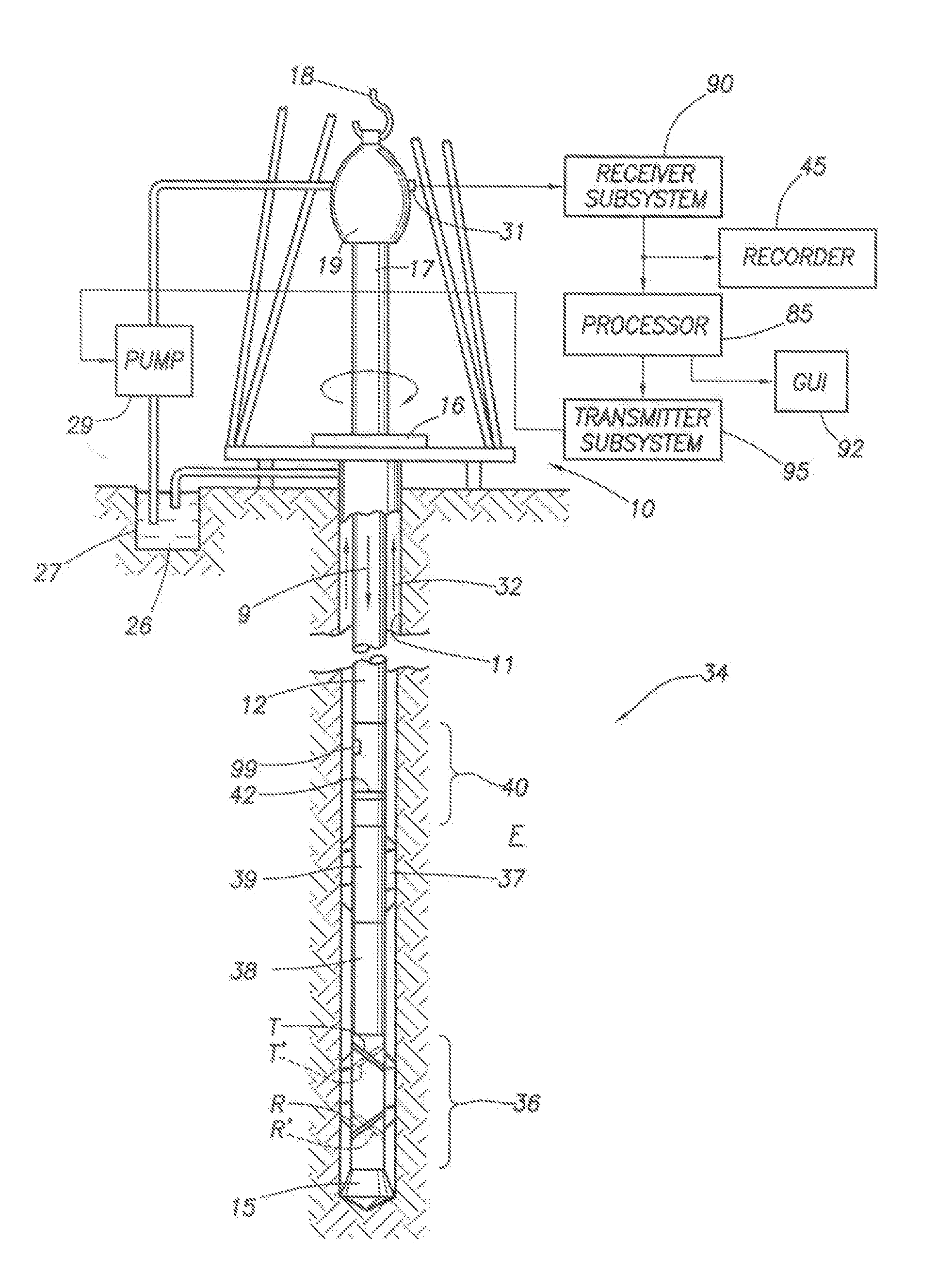
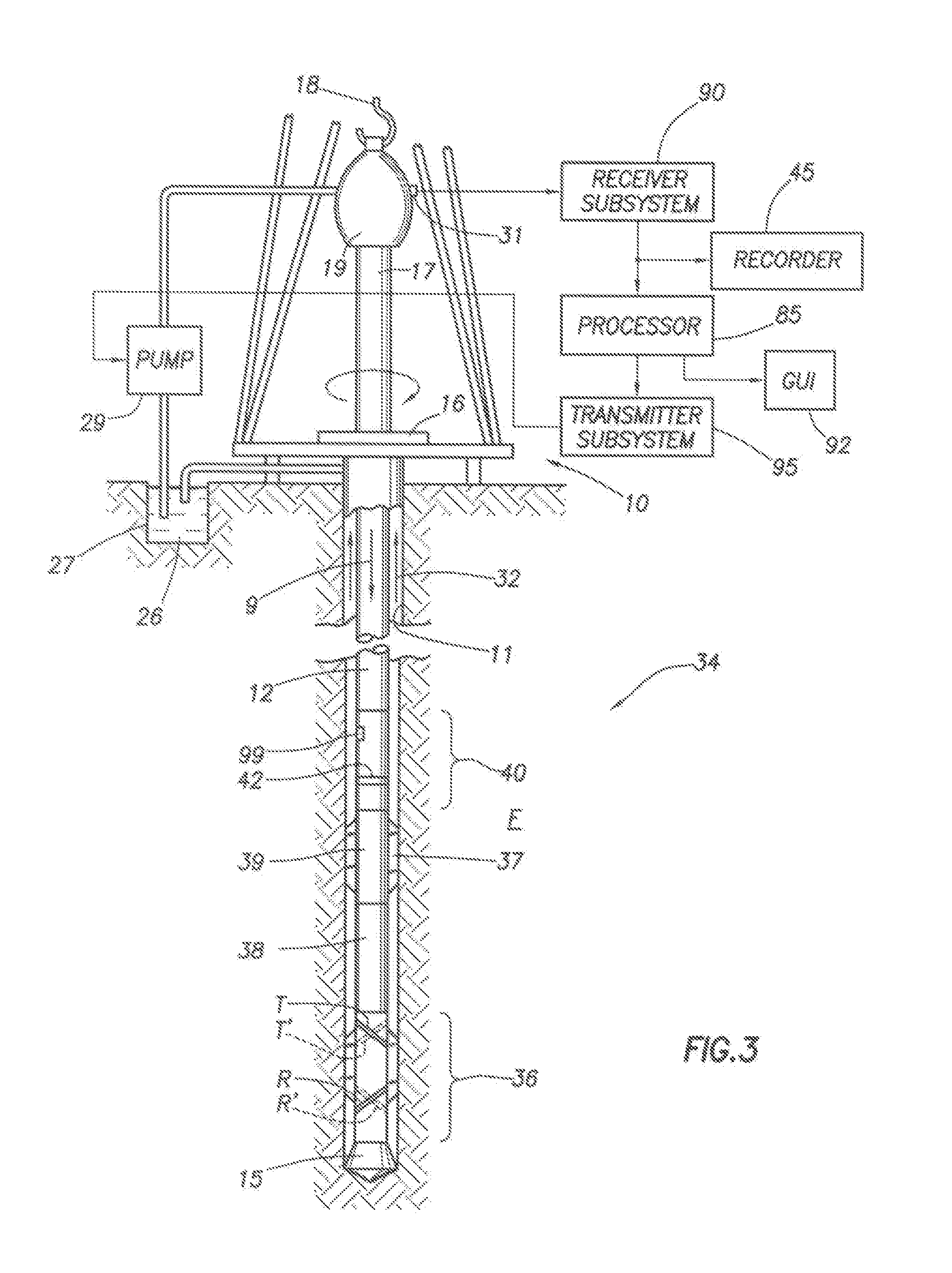
[0102]FIG. 3 illustrates a conventional drilling rig and drill string in which the present invention can be utilized to advantage. A land-based platform and derrick assembly 10 are positioned over a wellbore 11 penetrating a subsurface formation F. In the illustrated embodiment, the wellbore 11 is formed by rotary drilling in a manner that is well known. Those of ordinary skill in the art given the benefit of this disclosure will appreciate, however, that the present invention also finds application in directional drilling applications as well as rotary drilling, and is not limited to land-based rigs. It will further be appreciated that the present invention is not limited to “while-drilling” applications, but also has utility in wireline applications (as described further below).

[0103]A drill string 12 is suspended within the wellbore 11 and includes a drill bit 15 at its lower end. The drill string 12 is rotated by a rotary table 16, energized by means not shown, which engages a k...


PUM


Abstract

A method is described for characterizing a subsurface formation with a logging instrument disposed in a borehole penetrating the formation. The logging instrument is equipped with at least a transmitter system and a receiver system. The method entails positioning the logging instrument within the borehole so that the transmitter system and receiver system are disposed in the vicinity of a formation boundary of interest and measuring the azimuthal orientation of the logging instrument. Electromagnetic energy is transmitted into the formation using the transmitter system and signals associated with the transmitted electromagnetic energy are measured using the receiver system. The method further entails determining the relative azimuth of the formation boundary, composing a symmetrized directional measurement using the measured signals and the determined relative boundary azimuth, and determining the relative dip of the formation boundary using the composed directional measurement.

Description

CROSS-REFERENCE TO RELATED APPLICATIONS[0001]This application claims priority, under 35 U.S.C. § 119, to Provisional Application Ser. No. 60 / 493,747, filed on Aug. 8, 2003, incorporated by reference in its entirety.BACKGROUND OF THE INVENTION[0002]1. Field of the Invention[0003]The invention relates generally to the field of well logging. More particularly, the invention relates to improved techniques in which instruments equipped with antenna systems having transverse or tilted magnetic dipole-moment representations are used for electromagnetic measurements of subsurface formations and for defining the reservoir bedding structure and formation dip, as well as placing wells with respect to geological boundaries in a reservoir.[0004]2. Background of the Related Art[0005]Information that characterizes dips within a subsurface formation of interest is important for understanding the deposition environment of the sedimentary rocks, and for the development and execution of a well drillin...

Claims


Application Information

Patent Timeline
Patent Type & Authority Patents(United States)
IPC IPC(8): G01B3/08G01V3/28G01V3/18
CPCG01V3/28G01V3/30
Inventor OMERAGIC, DZEVATLI, QIMINGCHOU, LAWRENCEYANG, LIBOLIU, CHENGBINGSMITS, JAN
Owner SCHLUMBERGER TECH CORP
Why Eureka
Try Eureka