Pilot-operated pressure shut-off valve

a technology of pilot-operated pressure shut-off valve and valve body, which is applied in the direction of slide valve, functional valve type, instruments, etc., can solve the problem of no longer being within the sense of compact construction

Inactive Publication Date: 2007-04-17
BOSCH REXROTH AG
View PDF12 Cites 6 Cited by
  • Summary
  • Abstract
  • Description
  • Claims
  • Application Information

AI Technical Summary

Benefits of technology

[0006]The objective which is sought is achieved according to the invention wherein, the two pilot pistons, the two pilot springs and the two setting screws are arranged lying concentrically inside one another, with it being possible to adjust the two pilot pistons mechanically completely independently of each other. In this manner, the pilot valve arrangement is constructed very compactly with a low height. Only one valve housing is needed for the pilot valve arrangement. Instead of a conventional pilot valve arrangement which does not permit any independent setting of the two limit pressures from each other, said pilot valve arrangement can easily be constructed on a main stage. In comparison with a pilot valve arrangement having two valve bores for the two pilot pistons, the machining of the valve housing of a pilot valve arrangement according to the invention is substantially simplified, since only one valve bore is needed for the two pilot pistons. The compact, concentric arrangement of the pilot pistons, the pilot springs and the setting screws also makes possible a cartridge-type construction which it has hitherto not been possible to realize.
[0007]The complete mechanical independence of the two pilot pistons in respect of their movement possibilities can thus be achieved in a simple manner wherein the outer pilot piston is situated with an outer collar between two stops fixed on the housing, wherein the one stop is formed on a bushing inserted into the valve housing, and wherein the inner pilot piston penetrates the bushing and is situated with an outer collar between the bushing and a further insert placed in the valve housing.

Problems solved by technology

However, this no longer lies within the sense of a compact construction.

Method used


Image

  • Pilot-operated pressure shut-off valve
  • Pilot-operated pressure shut-off valve
  • Pilot-operated pressure shut-off valve

Examples


Embodiment Construction

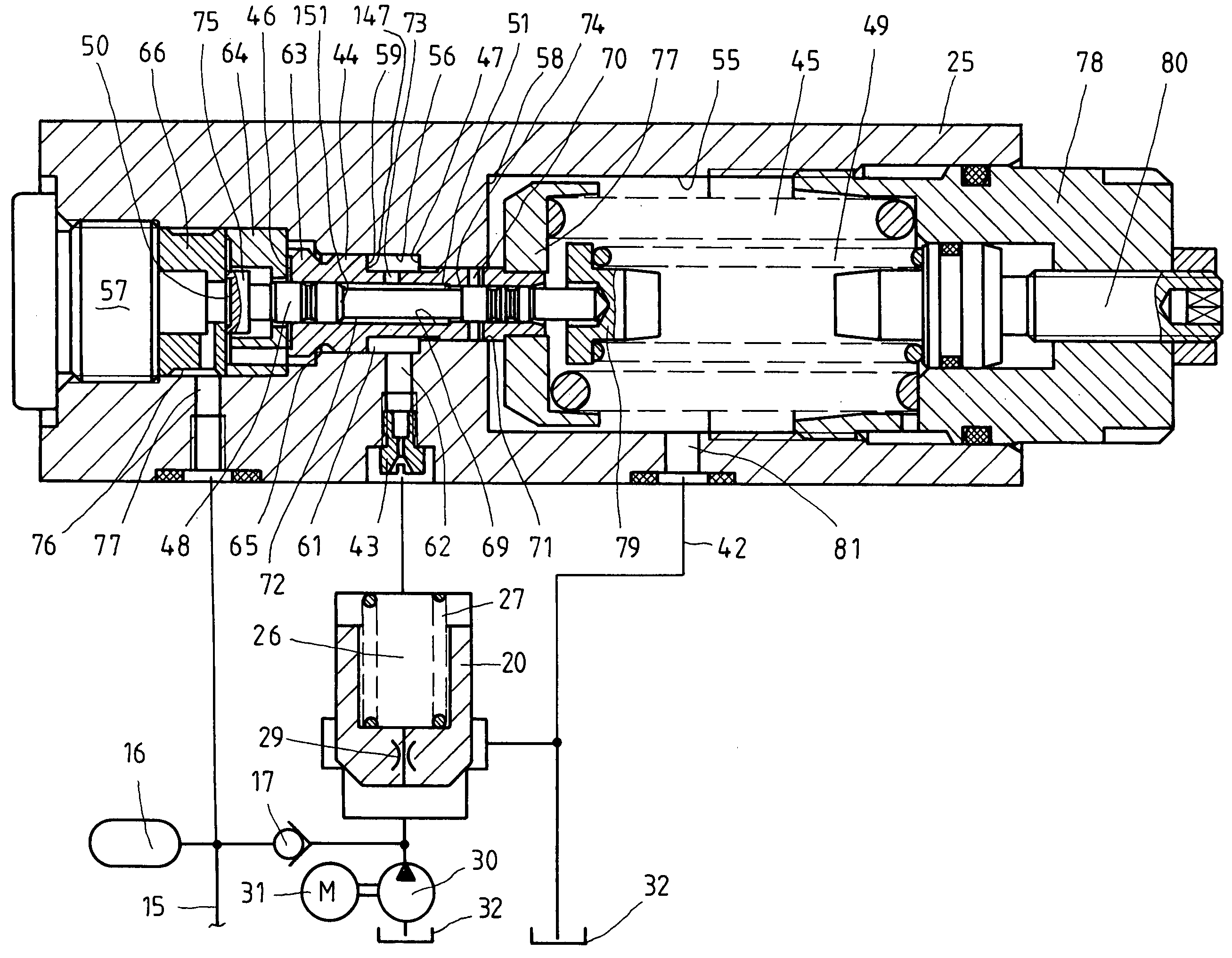
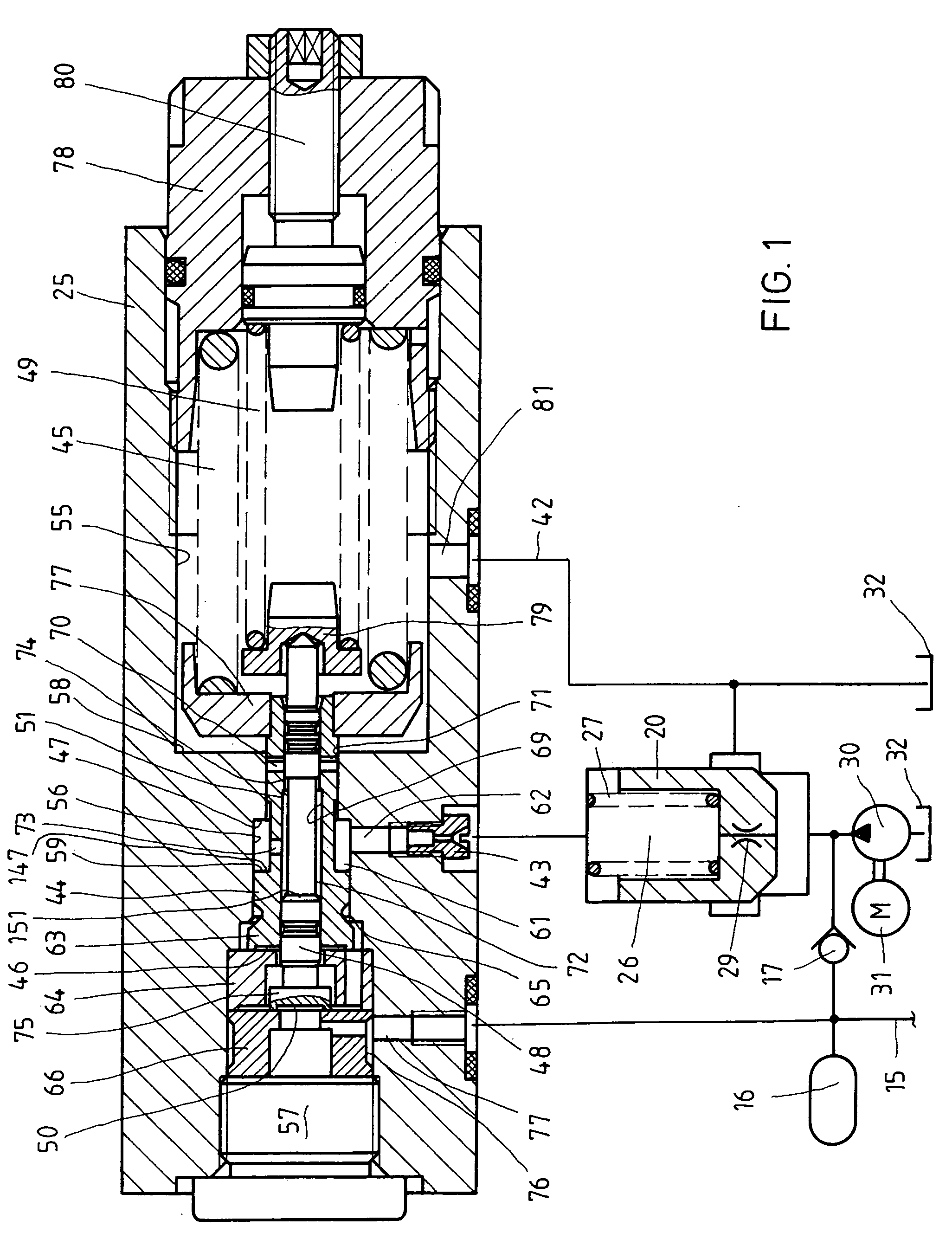
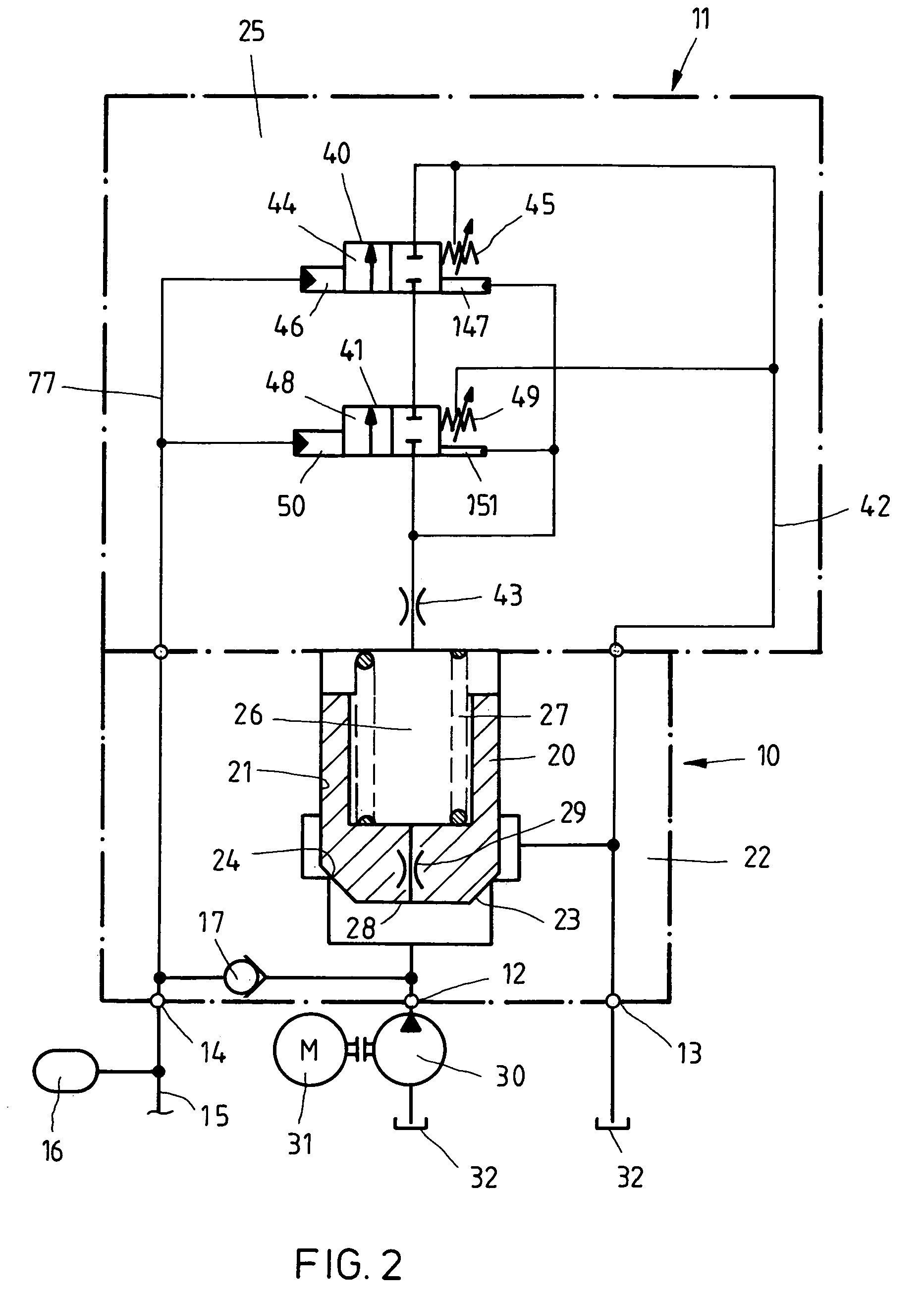
[0019]According to the connection diagram of FIG. 2, the pilot-operated pressure shut-off valve which is shown comprises a main stage 10 and a pilot valve arrangement 11, which are respectively indicated by a dash-dotted rectangle. The main stage 10 has an inlet connection 12, an outlet connection 13 and a system connection 14. Leading off from the latter is a system line 15 to which a hydraulic accumulator 16 and directional control valves (not illustrated specifically) for controlling hydraulic consumers are connected. The inlet connection 12 and the system connection 14 are connected to each other via a nonreturn valve 17 which opens from the inlet connection toward the system connection. The main stage 10 includes a main control piston 20 with which a throughflow cross section between the inlet connection 12 and the outlet connection 13 can be opened and closed. The main control piston is guided on a first diameter in a bore 21 in the housing 22 of the main stage and is able to ...


PUM


Abstract

A pilot-operated pressure shut-off valve having a main control piston which, when an upper system limit pressure in the hydraulic system is reached, connects an inlet, via which pressure medium can be fed to a hydraulic system, to an outlet by taking up a first switching position and, when a lower system limit pressure is reached, separates from the outlet by taking up a second switching position. The pressure shut-off valve has a pilot valve arrangement by which the fluidic connection of a control space adjacent to the main control piston can be changed in order to control the main control piston, and which has a valve housing, with a first pilot piston and a second pilot piston accommodated within the first pilot piston for compact construction and capability to adjust the two pilot pistons mechanically completely independently of each other.

Description

FIELD AND BACKGROUND OF THE INVENTION[0001]The invention relates to a pilot-operated pressure shut-off valve which, when an upper system limit pressure is reached in a hydraulic system having a hydraulic accumulator, connects an inlet feeding the hydraulic system to an outlet to a tank and separates this connection when removal of hydraulic fluid from the hydraulic accumulator has caused the system pressure to drop to a lower system limit pressure and which has a main control piston and, in order to control the main control piston, a pilot valve arrangement having two pilot pistons and two pilot springs, the adjustment of which makes it possible for the upper system limit pressure and the lower system limit pressure to be set independently of each other.[0002]A pilot-operated pressure shut-off valve of this type is disclosed, for example, in DE 41 12 065 A1 or in DE 36 08 100 C2. In the case of the pressure shut-off valve according to DE 41 12 065 A1, the pilot valve arrangement com...

Claims


Application Information

Patent Timeline
Patent Type & Authority Patents(United States)
IPC IPC(8): F16K17/00F16K3/24F15B1/027F15B11/08F16K31/363
CPCF15B1/027F15B1/0275Y10T137/2625Y10T137/263Y10T137/2635Y10T137/7766Y10T137/777
Inventor KRENZER, GUNTERMEYER, KARL JOSEFLAUER, PETER
Owner BOSCH REXROTH AG
Why Eureka
Try Eureka