Method for glass separation for flat panel displays

a flat panel display and glass panel technology, applied in the direction of manufacturing tools, instruments, transportation and packaging, etc., can solve the problems of difficult control of the direction of separation cracks, more difficult to handle glass panels, and defects in the final glass panels, so as to minimize separation defects in glass panels, accurately position the panel, and more consistent separation

Inactive Publication Date: 2007-04-17
GE MEDICAL SYST GLOBAL TECH CO LLC
View PDF30 Cites 13 Cited by
  • Summary
  • Abstract
  • Description
  • Claims
  • Application Information

AI Technical Summary

Benefits of technology

[0006]A method and apparatus are provided for separating glass panels that provide more consistent separation and minimize separation defects in the glass panel. A preferred embodiment of the present invention includes a separation handle that applies the minimal pressure necessary to separate the glass evenly along the unwanted edge portions to be removed.
[0007]In a preferred embodiment, the scored panel is placed upon a stage, which is covered by an electrically dissipative material to prevent any electrostatic discharge from destroying the semiconductors etched in the glass panel. Nitrogen gas is pumped along the underside of the glass panel, causing the glass panel to float above the stage during positioning. Locating pins are inserted into holes located along the side of the stage to accurately position the panel. This allows successive glass panels to be placed in the same location on the stage, allowing for more consistent separation.
[0008]Once the glass panel is in place, a vacuum sucks the panel against the stage, holding the panel tightly against the stage. The separation handle is then inserted over the edge portion to be removed. A force gauge is attached to the separation handle to measure the amount of force applied to the glass panel. The force is incrementally increased until slow, controlled separation of the edge is achieved. The level of force is maintained until separation is complete. By using the minimal force in separating the glass, the likelihood of separation defects is greatly reduced. The stage is mechanically rotated without lifting or repositioning the glass panel before each subsequent separation, reducing the risk of ESD.

Problems solved by technology

Oftentimes, semiconductor devices are formed on the glass panel, making it even more difficult to handle the glass panels because touching the active area of the panel may result in damaging the semiconductor devices.
This conventional method does not allow the person separating the glass to provide a controllable amount of force evenly along the entire edge to be separated, thereby making it difficult to control the direction of the separation crack.
Therefore, manual separation often results in defects within the final glass panel.
These defects may even be visible to the naked eye, and can reduce the yield of the product.
Furthermore, excessive handling of the glass panel may cause electrostatic damage (ESD) to the circuitry.
A glass panel with x-ray imager structures formed on it can cost tens of thousands of dollars to produce, but can be completely ruined if not correctly separated.

Method used


Image

  • Method for glass separation for flat panel displays
  • Method for glass separation for flat panel displays
  • Method for glass separation for flat panel displays

Examples


Embodiment Construction

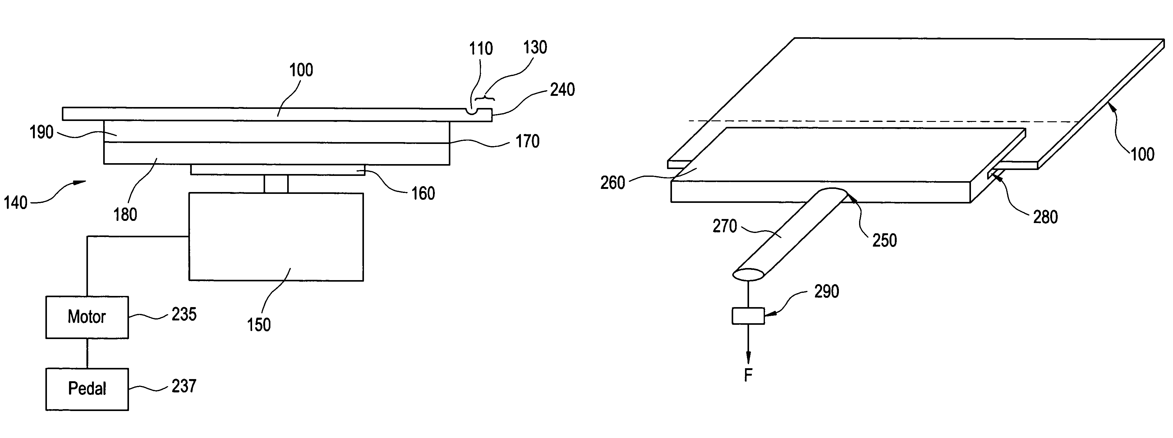
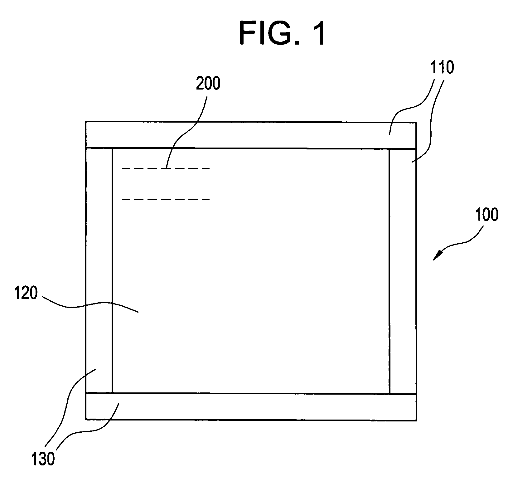
[0014]FIG. 1 illustrates a glass panel 100, such as a glass panel used in liquid crystal displays or X-ray imagers. Such glass panels 100 may range in size, such as from about 2 to 60 centimeters on a side, and may range in thickness, such as from about 0.5 to 2 millimeters in thickness. Typical panels are made from the Corning Corporation's Code 7059 or Code 1737 glass. The original glass panel 100 used in the manufacturing process is larger than the final product, and thus the unwanted edges must be separated to produce a final product with desired dimensions. As seen in FIG. 1, the glass panel 100 is cut along score lines 110, thereby defining an inner panel 120 of desired dimension and edge portions 130, which are to be removed. The glass panel 100 may be scored with a diamond or tungsten carbide tool, and may be scored at anytime prior to the separation process.

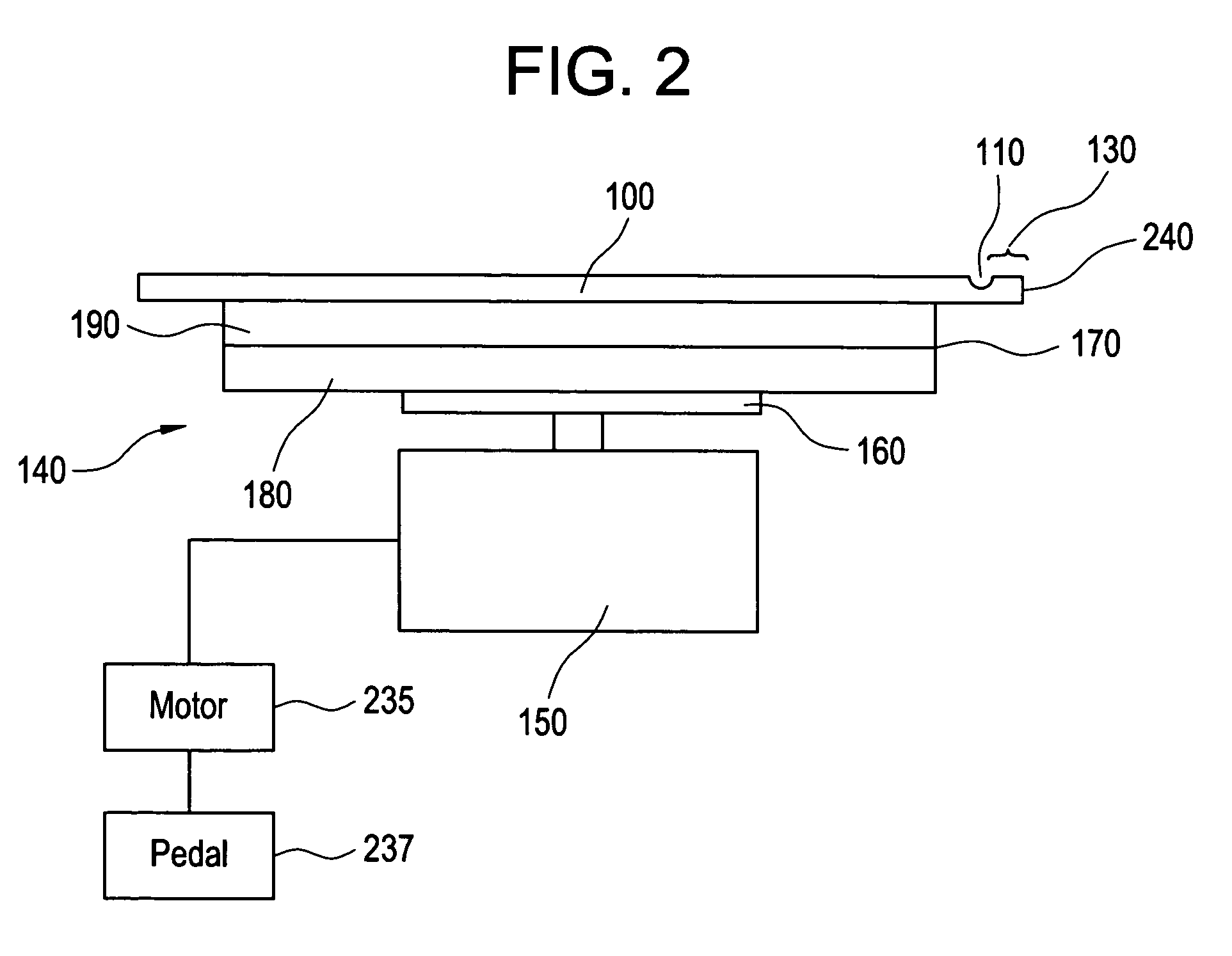
[0015]FIG. 2 illustrates a glass separating apparatus 140 for separating the unwanted edge portion 130 of the glass pa...


PUM

PropertyMeasurementUnit
thicknessaaaaaaaaaa
sizeaaaaaaaaaa
tensile strengthaaaaaaaaaa

Abstract

A method and apparatus for separating glass panels that minimizes process failures and improves separation process consistency by utilizing a separation handle which applies the minimal pressure necessary to remove the edge portion from the glass panel. The glass panel is cut along the score line, which outlines the edge portions of the glass panel to be removed. The panel is placed upon the separating apparatus, which pumps nitrogen along the underside of the glass panel, causing the glass panel to float above the apparatus. Locating pins are inserted to position the panel on the stage. Once the glass panel is in place, a vacuum sucks the panel against the stage, holding the panel tightly against the stage. The separation handle is then inserted over the edge portion to be removed. A measured force is applied to the handle, with the force incrementally increased until the slow, controllable separation of the edge is achieved. This level of force is maintained until separation is complete.

Description

CROSS REFERENCE TO RELATED APPLICATIONS[0001]The present application is a divisional of U.S. application Ser. No. 09 / 691,368, entitled “Apparatus and Method for Glass Separation for Flat Panel Displays,” filed Oct. 18, 2000 now U.S. Pat. No. 6,962,276, which is hereby incorporated by reference in its entirety.BACKGROUND OF THE INVENTION[0002]The preferred embodiments of the present invention generally relate to a method and apparatus for separating glass panels such as those used in flat panel displays.[0003]Liquid crystal displays or light imagers, such as those used in X-ray imaging systems, require the manufacture of circuitry on thin glass panels, for example comprising amorphous silicon transistors and photodiodes. The circuitry may range from as small as two centimeters to more than sixty centimeters on a side. Oftentimes, semiconductor devices are formed on the glass panel, making it even more difficult to handle the glass panels because touching the active area of the panel ...

Claims


Application Information

Patent Timeline
Patent Type & Authority Patents(United States)
IPC IPC(8): B26F3/00C03B33/03C03B33/033C03B33/07G02F1/1333
CPCC03B33/03C03B33/033C03B33/07B65G2249/04G02F1/133351Y02P40/57Y10T225/371Y10T225/30Y10T225/325Y10T225/12Y10T225/10C03B37/12
Inventor MAREK, HENRY S.KWASNICK, ROBERTHORACIO-FLORES MOCTEZUMA, RUBENMAYDANICH, FYODOR I.
Owner GE MEDICAL SYST GLOBAL TECH CO LLC
Why Eureka
Try Eureka