Waste liquid treating device and liquid ejecting apparatus incorporating the same

a technology of liquid ejecting apparatus and waste liquid treatment device, which is applied in the field of waste liquid treatment device and liquid ejecting apparatus incorporating the same, can solve the problems of ink leakage out of the printer, deterioration of printing quality, and overflowing out of the groove hol

Active Publication Date: 2007-04-17
SEIKO EPSON CORP
View PDF18 Cites 51 Cited by
  • Summary
  • Abstract
  • Description
  • Claims
  • Application Information

AI Technical Summary

Benefits of technology

[0013]It is therefore an object of the invention to provide a liquid ejecting apparatus, in which waste liquid disposed to a waste liquid absorber provided in a groove hole can be smoothly lead to a waste liquid tray arranged in a lower portion of the apparatus, without involving cost increasing or remarkable design change.

Problems solved by technology

If such a first waste liquid absorber is not provided, there is a possibility that the ink disposed into the groove hole might become an ink mist to deteriorate printing quality or might stick to the driving components of a printer to disturb a normal printing operation.
If the printer is greatly inclined in the handling or transportation of a user in such a state, for example, the ink held in the lower part of the first waste liquid absorber concentrates on the end of a platen and might overflow out of the groove hole in the worst case.
When such a phenomenon arises, there is a possibility that the components of the printer (for example, a driving system or an electric system) might be adversely influenced, and furthermore, the ink might leak out of the printer.
Accordingly, there is a possibility that the ink might be maintained in a large amount in the first waste liquid absorber for a long period of time.
In the case in which an ink which is easily solidified, for example, a pigment based ink is used, particularly, there is a possibility that the ink might be held in the first waste liquid absorber for a long period of time and the ink solidified on the surface of the first waste liquid absorber might be thus deposited to deteriorate the absorbing capability of the first waste liquid absorber.
However, a component having such a configuration that the first waste liquid absorber and the second waste liquid absorber are integrated has a novel configuration which has not been conventionally obtained.
For this reason, there is an anxiety that the design of an ink jet recording apparatus might be changed considerably when the such a component is employed.
There is an anxiety that a cost might be increased due to the change in a design and a production efficiency might be reduced.

Method used


Image

  • Waste liquid treating device and liquid ejecting apparatus incorporating the same
  • Waste liquid treating device and liquid ejecting apparatus incorporating the same
  • Waste liquid treating device and liquid ejecting apparatus incorporating the same

Examples


first embodiment

[0150]the invention will be described below with reference to FIGS. 1 through 6.

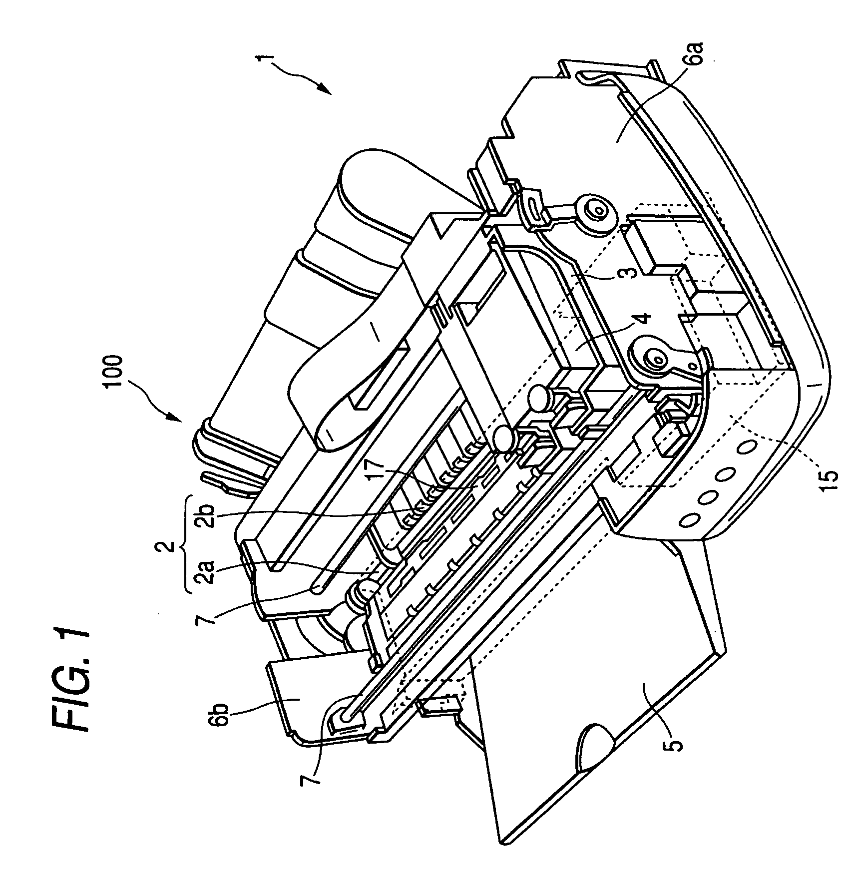
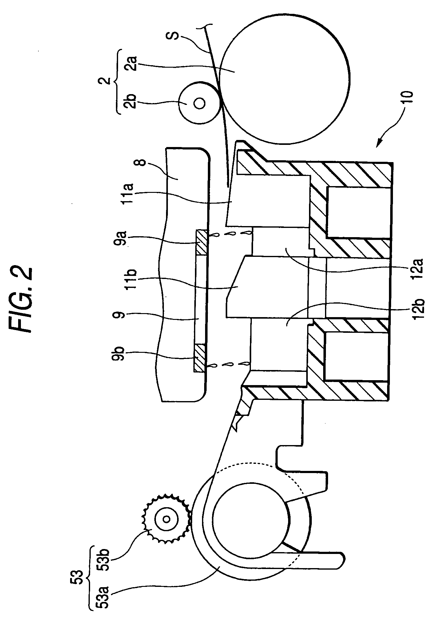
[0151]In FIG. 1, an ink jet printer 100 (hereinafter referred to as “printer”) as a liquid ejecting apparatus comprises a feeder 1 to feed an uppermost one of sheets stacked thereon toward an ink jet recording head 8 (which will be hereinafter referred to as a “recording head”: see FIG. 2) provided under a carriage 3, at which recording is performed, and the sheet is ejected to a sheet discharge stacker 5 after the recording is carried out.

[0152]The carriage 3 mounts an ink cartridge 4 which supplies ink to the recording head 8. Moreover, the carriage 3 inserts a carriage guide shaft 7 provided between side frames 6a and 6b constituting the base member of the printer 100 and is guided in a primary scanning direction by the carriage guide shaft 7. The carriage 3 is reciprocated in the primary scanning direction by a driving member which is not shown.

[0153]In FIG. 1, a lower right side is defined as a “hom...

second embodiment

[0175]Next, an ink jet printer (hereinafter referred to as a “printer”) 200 as a liquid ejecting apparatus according to the invention will be described with reference to FIGS. 7 to 11.

[0176]The printer 200 comprises a feeder in the rear part of the apparatus (an upper left part in FIG. 7) which is not shown in detail, and feeds cut-form sheets one by one to the recording section (see FIG. 9). Moreover, the feeder includes a rolled sheet holder 228 so that a rolled sheet R can be set to be freely rotatable. In the embodiment, the medium which can be fed by the feeder will be collectively referred to as a sheet S.

[0177]The recording section provided on the downstream side of the feeder includes a delivery roller having a delivery driving roller 201a and a delivery driven roller 201b as shown in FIG. 9. The delivery driving roller 201a is rotated by a driving motor which is not shown and the delivery driven roller 201b is rotated via a pressure contact with the delivery driving roller ...

third embodiment

[0211]Next, the invention will be described with reference to FIGS. 17 to 20. As shown in FIG. 17, an ink jet printer 311 as a liquid ejecting apparatus comprises a printer body 312 and a feeder 312a provided on the rear side of the printer body 312. Sheets S stacked on the feeder 312a are fed into the printer body 312 one by one.

[0212]The printer body 312 includes a case 313 having the shape of an almost rectangular parallelepiped and a carriage guide shaft 314 is provided between both of left and right side plates 313a and 313b of the case 313. A carriage 315 is slidably supported on the carriage guide shaft 314. The carriage 315 is coupled to a carriage motor 316 through a timing belt 317 and is driven in a direction of an arrow in the drawing, that is, a primary scanning direction by the driving operation of the carriage motor 316.

[0213]Moreover, an ink cartridge 318 for storing ink (liquid) is removably attached to the upper side of the carriage 315, and a recording head 319 as...


PUM


Abstract

A liquid ejecting head is operable to move in a first direction. A platen is opposed to the liquid ejecting head to support an object to which a liquid droplet is ejected from the liquid ejecting head and to define a gap between the liquid ejecting head and the object. The platen is formed with a groove hole to which a liquid droplet deviated from an edge of the object is disposed, and through holes formed in a bottom portion of the groove hole and arranged in the first direction. A tray member is arranged below the platen to receive liquid dropped through the through holes. A first liquid absorber is provided in the groove hole. A second liquid absorber is provided in the tray member. At least one liquid leading member extends through at least one of the through holes to lead liquid absorbed by the first liquid absorber to the second liquid absorber.

Description

CROSS REFERENCE OF THE APPLICATION[0001]This is a continuation-in-part application of U.S. patent application Ser. No. 10 / 458,749 filed on Jun. 11, 2003 now U.S. Pat. No. 6,910,757.BACKGROUND OF THE INVENTION[0002]The present invention relates to a liquid ejecting apparatus such as an ink jet recording apparatus which can execute so-called marginless printing by disposing ink away from the end of a target medium. Other than recording apparatuses such as printers, copiers, facsimile machines, the liquid ejecting apparatus includes an apparatus for ejecting liquid, in place of ink, from a liquid ejecting head onto an object on which the ejected liquid is landed.[0003]Examples of the liquid ejecting head include a colorant ejecting head to be used for manufacturing a color filter such as a liquid crystal display, an electrode material (conductive paste) ejecting head to be used in the formation of an electrode such as an organic EL display or a surface emitting display (FED), a biologi...

Claims


Application Information

Patent Timeline
Patent Type & Authority Patents(United States)
IPC IPC(8): B41J2/165B41J2/17
CPCB41J2/16523B41J2/1721B41J2002/1742
Inventor KANAMITSU, MASATOMOKATAGIRI, NARUHIKOWADA, HAJIMEHABA, KEISUKEARAYA, MIDORIISONO, MASAHIROKOBAYASHI, HIKARUTAKEDA, KAZUHISAISHIHARA, KENJIROTEZUKA, SEIJIKANETA, SATOSHISATO, TAKASHI
Owner SEIKO EPSON CORP
Why Eureka
Try Eureka