
Granular and aggregate blending, cooling and screening rotary drum

a technology of rotary drums and granular aggregates, applied in the field of rotary drums, can solve the problems of insufficient heat removal of hot granular products by exposure to airflow only at the discharge end, and achieve the effects of reducing thrust loads, reducing wear, and reducing the load

Inactive Publication Date: 2007-04-17
DIDION TECHNOLOGIES LLC
View PDF21 Cites 28 Cited by
  • Summary
  • Abstract
  • Description
  • Claims
  • Application Information

AI Technical Summary

Benefits of technology

[0011]It is, therefore, a further object of this invention to provide a rotary drum that reduces scrap and cleaning cost within a plant, due to the lower sand temperature and improved sand conditions.
[0018]Another object is to utilize optional stainless steel segments that form screens, in the form of panels, to provide better screening of the sand and granular material, and which furnishes better wear resistance, yet provides screen segments that are easily replaced.

Problems solved by technology

However, it has been found that the removal of heat from hot granular products by exposure to an airflow only at the discharge end is insufficient to reduce the temperature of the granular products to near ambient temperatures.

Method used


Image

  • Granular and aggregate blending, cooling and screening rotary drum
  • Granular and aggregate blending, cooling and screening rotary drum
  • Granular and aggregate blending, cooling and screening rotary drum

Examples


Embodiment Construction

[0032]The following detailed description illustrates the invention by way of example and not by way of limitation. The description clearly enables one skilled in the art to make and use the invention, describes several embodiments, adaptations, variations, alternatives, and uses of the invention, including what is presently believed to be the best mode of carrying out the invention.

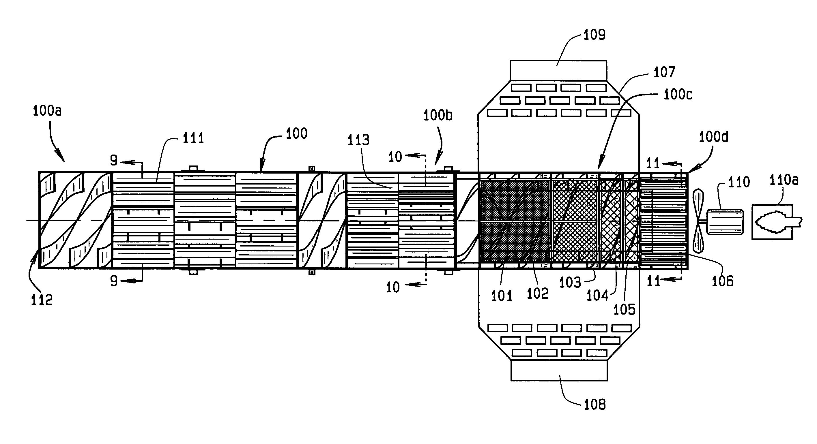
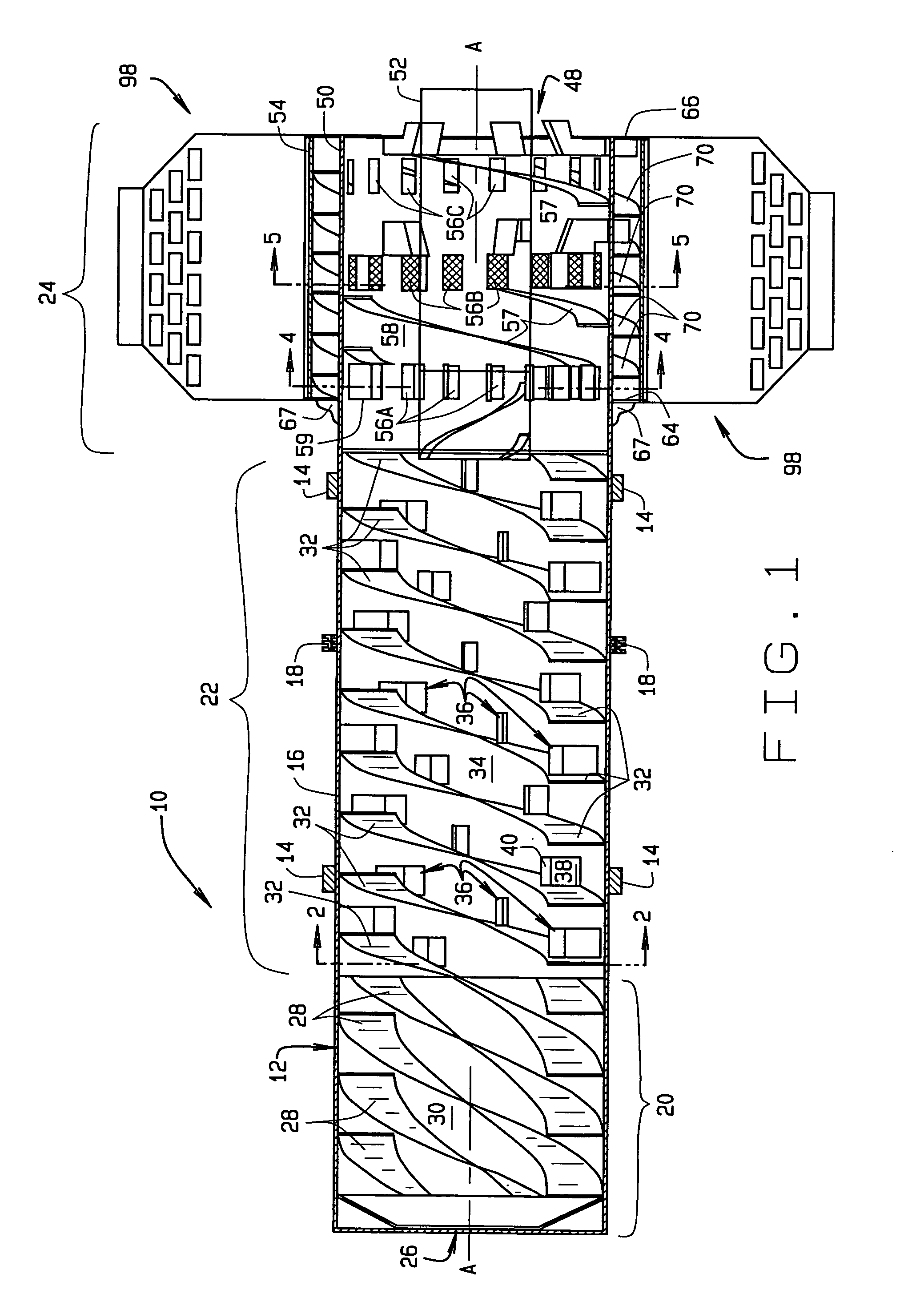
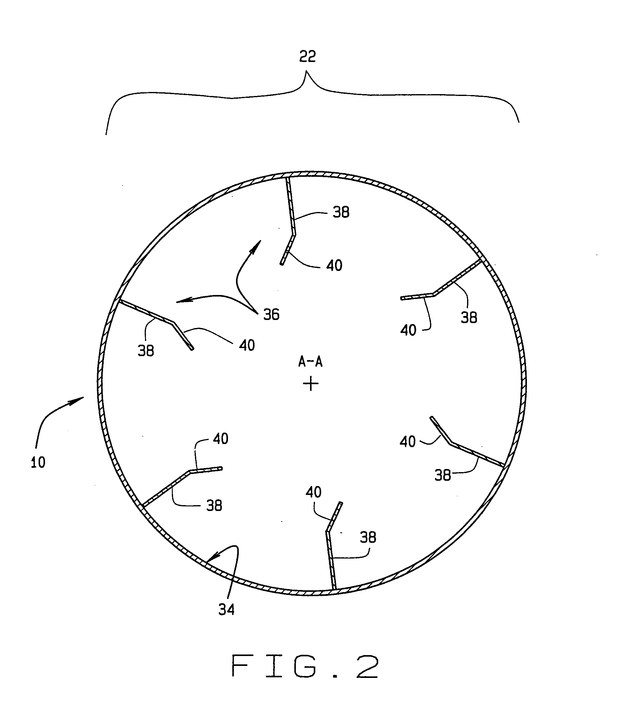
[0033]Turning to FIG. 1, a rotary drum of the present invention for effecting the blending and cooling of granular product is shown generally at 10. The rotary media drum 10 comprises a cylindrical drum body 12, which is includes a plurality of spaced circumferential drum assembly tires 14 disposed on an external surface 16. The circumferential drum assembly tires support the rotary drum 10 on a conventional base (not shown). Correspondingly, a circumferential sprocket 18 on the external surface 16 engages a conventional drive mechanism (not shown) in the conventional base to drive the rotary drum 10 at a...


PUM

PropertyMeasurementUnit
sizeaaaaaaaaaa
diameteraaaaaaaaaa
lengthaaaaaaaaaa

Abstract

A rotary drum configured for the efficient blending, cooling, and screening of granular products having an outer cylindrical shell, an intake end, and an exit or discharge end. The rotary drum is normally rotated at a predetermined speed by a conventional drive package. Disposed on an inner surface of the cylindrical shell is a plurality of compound helical flights and scoops or lifts, configured to blend granular product as it cascades from the intake end to the discharge or exit end of the rotary drum. A coaxially disposed cylindrical air passage adjacent the discharge end of the rotary drum, comprising an inner cylinder, that directs a counter flow of cooling air through the rotary drum towards the intake end, for cooling the cascading granular product as it approaches the screening segment of the rotary drum. The rotary drum having a plurality of discharge ports and grading screens just before its discharge end, provided in the surface of the outer cylindrical shell adjacent to the discharge end, to allow for the passage of air for attaining dust collection, while the counter flowing cooling air passes through the internally arranged inner cylinder to achieve the cooling effect within the rotary drum.

Description

CROSS-REFERENCE TO RELATED APPLICATIONS[0001]This continuation-in-part patent application claims priority to the non provisional patent application having Ser. No. 10 / 336,927, which was filed on Jan. 7, 2003, now U.S. Pat. No. 6,896,400.BACKGROUND OF THE INVENTION[0002]The present invention relates generally to a rotary drum as used in the granular product drying field, and having a major application for the treatment of heated and moist granular products such as mold sands, grains, and fertilizers as to achieve the reclaiming, cooling, and blending of the mold granular product and in particular, to a dust collection hood and discharge chute configured to convey multiple air streams through the rotary drum for the cooling of the granular product.[0003]There are a variety of prior patents that have been obtained upon various styles of rotary drums for use in the metal casting industry. For example, one of the early embodiments is that which is shown in U.S. Pat. No. 3,998,262 to Char...

Claims


Application Information

Patent Timeline
Patent Type & Authority Patents(United States)
IPC IPC(8): B01F9/02B01F15/06B01F29/63B01F29/60F26B11/02F26B11/04
CPCB01F9/06B01F15/063F26B11/026F26B11/0477B01F3/18B01F2015/061B01F23/60B01F29/63B01F2035/98B01F35/91
Inventor DIDION, CHARLES J.
Owner DIDION TECHNOLOGIES LLC
Learn More