
System and method for controlling a processor including a digester utilizing time-based assessments

a technology of time-based assessment and control system, applied in the direction of process and machine control, computation using non-denominational number representation, green and white liquor treatment, etc., to achieve the effect of minimizing or avoiding instabilities

Inactive Publication Date: 2007-04-17
METABO AUTOMATION USA
View PDF3 Cites 10 Cited by
  • Summary
  • Abstract
  • Description
  • Claims
  • Application Information

AI Technical Summary

Benefits of technology

"The present invention provides an improved system and method for controlling processing equipment, particularly in the pulp and pager industry. The system and method minimize or avoid instabilities caused by disturbances or changes to the processors or process conditions, resulting in better quality and production. The control does not require complex predictive models or detailed process knowledge, reducing the risk of production loss. It also reduces long-term disturbances on processors and can be used for various processors such as pulp digesters and bleaching processors. The control uses a tunable time window to see if the processor is responding to a process change and compensates for any dead time related to the process. The invention provides a better understanding of the process and reduces the impact of disturbances on the quality and production of the processor."

Problems solved by technology

For example, processors in the pulp and paper mill industry represent applications where a complex predictive model, for example a neural network based control, would not be an accepted practice as the pulp and paper mill industry can not afford to risk the production of more than 1,300 tons per day of digested pulp on complex software installed on a processor controls which can not be routinely upgraded, routinely monitored, and installed on site.

Method used


Image

  • System and method for controlling a processor including a digester utilizing time-based assessments
  • System and method for controlling a processor including a digester utilizing time-based assessments
  • System and method for controlling a processor including a digester utilizing time-based assessments

Examples


Embodiment Construction

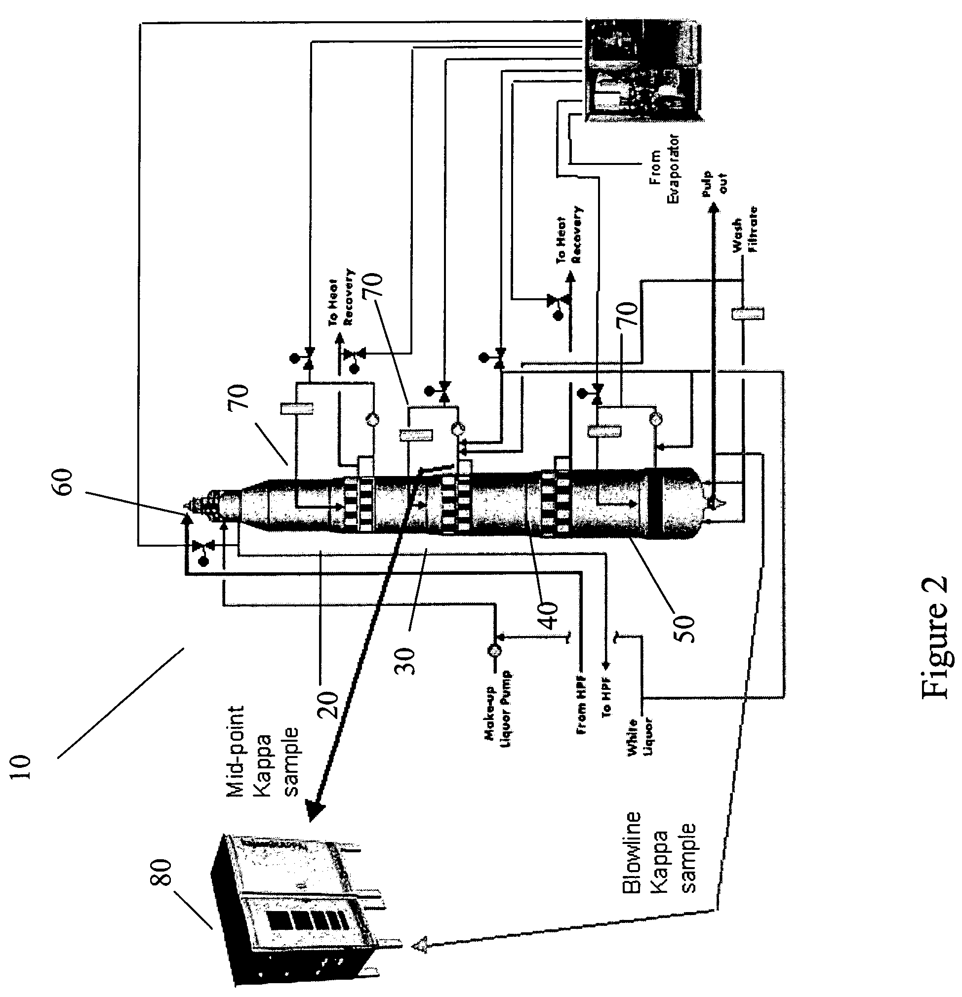
[0032]Referring now to the drawings, wherein like reference numerals designate identical or corresponding parts throughout the several views, and more particularly to FIG. 2 thereof, FIG. 2 is a schematic diagram of a processor including a controller 80 according to the present invention. The processor in FIG. 2 is schematically represented as a pulp digester 10, but could equally well typify other pulp mill processes such as for example the oxygen delignifcation processors, the bleaching processors, and the causticizers mentioned above in which reactant products from the processes are monitored to provide control.

[0033]As shown illustratively in FIG. 2, a pulp digester 10 of the present invention includes sequential cooking sections illustrated here by an upper cooking section 20, a mid-cooking section 30, an extended-cooking section 40, and a discharge section 50. White liquor, including for example the aforementioned sodium hydroxide and hydrosulfide, is introduced into the pulp ...


PUM

PropertyMeasurementUnit
retention timeaaaaaaaaaa
Kappa numberaaaaaaaaaa
timeaaaaaaaaaa

Abstract

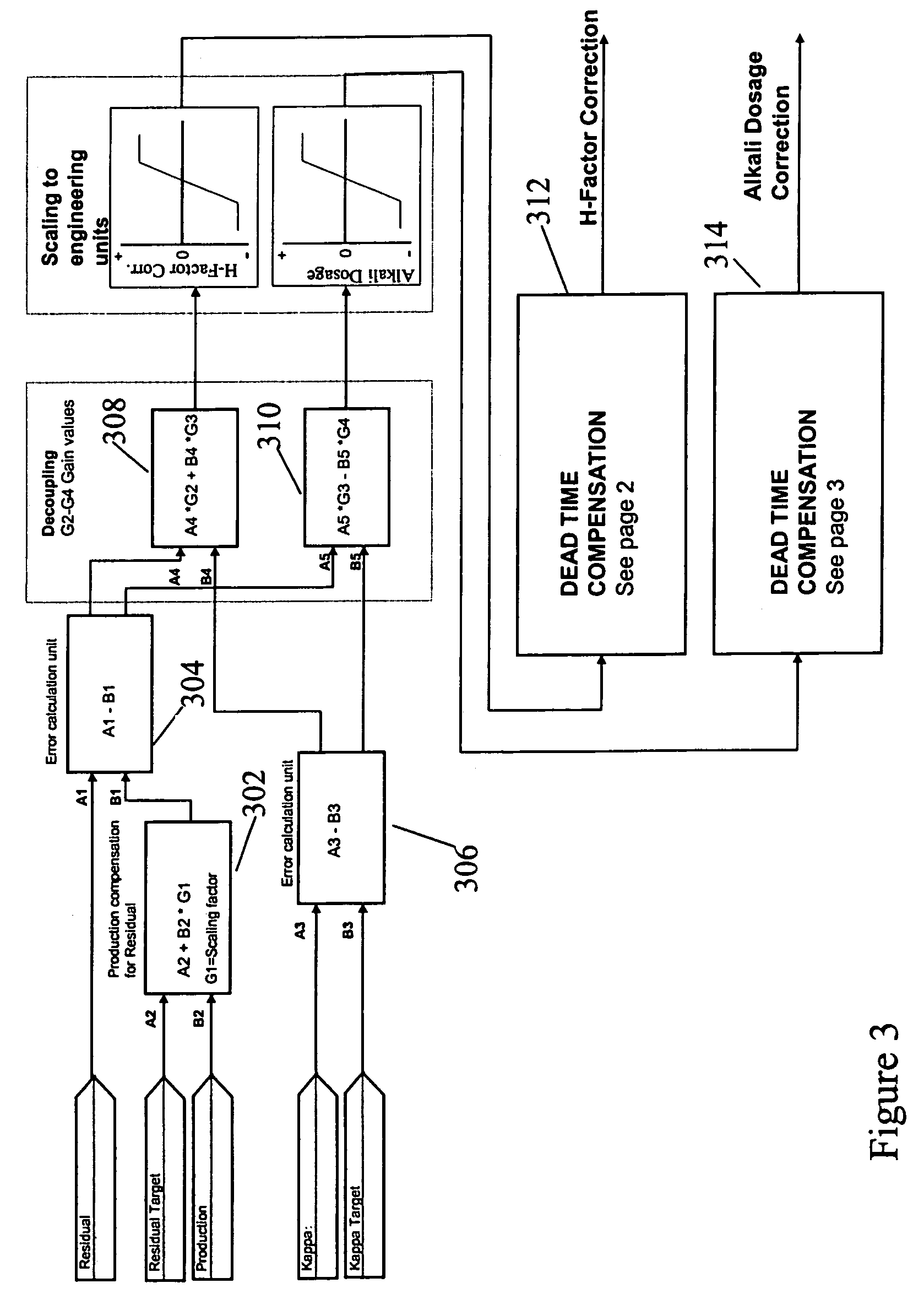
A system for controlling a processor having at least one sampling port connected to a stage of the processor in order to sample a reactant product from the processor. The system includes a controller configured to control a processing parameter of the processor based on measurements of at least one property of the reactant product such that changes to the processing parameter maintain a target value for the at least one property of the reactant product. The system further includes a dead time compensator. The dead time compensator is configured, based upon a prescribed dead time related to a time before at least one effect of at least one change to the processing parameter is fully realized, to evaluate the reactant product to determine if the effect has been realized at a plurality of sequential times offset from the dead time.

Description

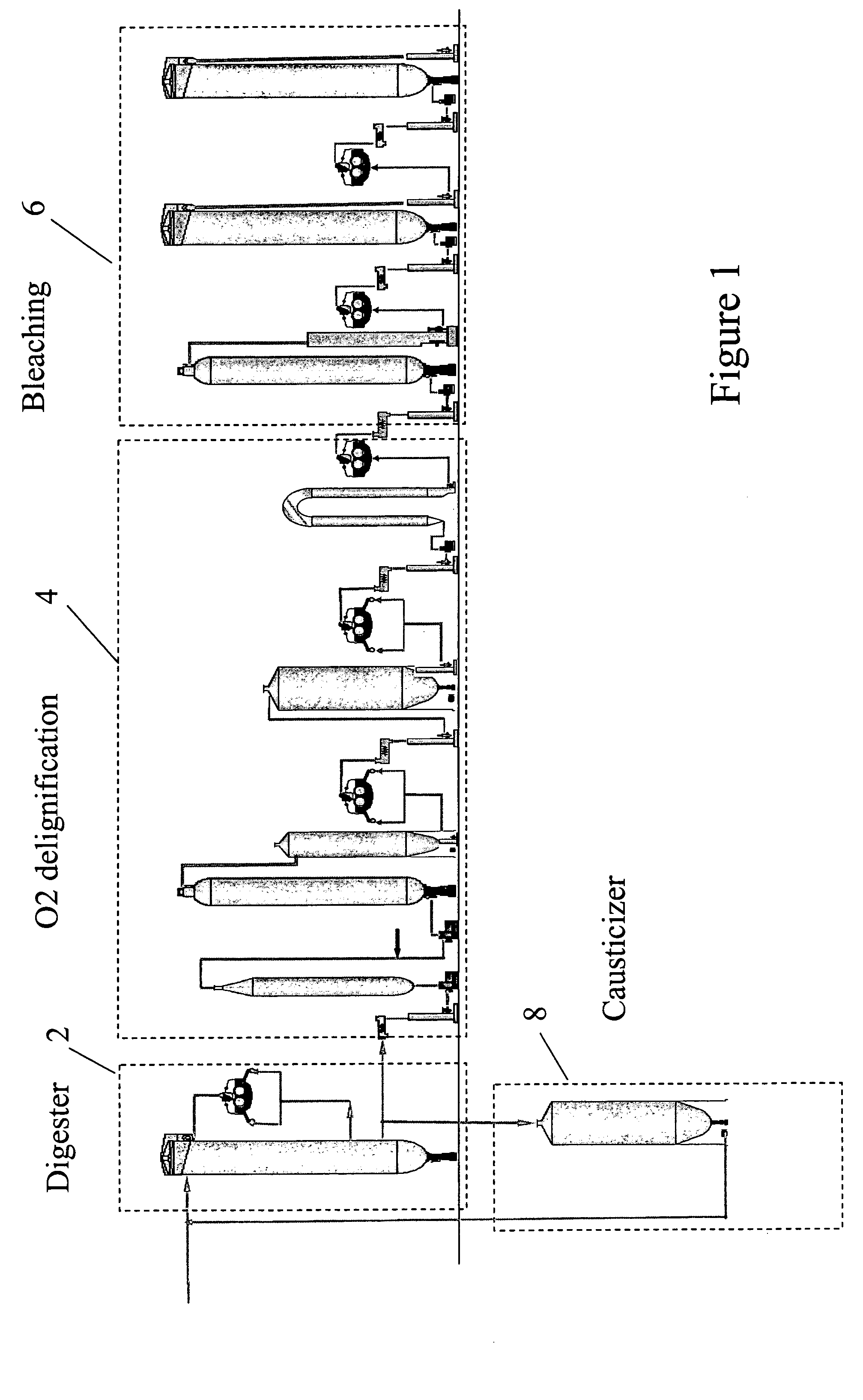
DISCUSSION OF THE BACKGROUND[0001]1. Field of the Invention[0002]This invention relates to the control of processes and processing equipment, and in particular production processes / equipment for use in the pulp and paper industry. The invention is particularly advantageous for pulp digesters.[0003]2. Background of the Invention[0004]Processors storing large quantities of chemically reactive (and some cases reacting) fluids are utilized extensively throughout the paper and pulp industry. Typically, the processes and equipment are “in-line” with the output from one processor providing the input to a subsequent downstream processor. Each processor in the paper and pulp industry processes a large tonnage of product. For example, a continuous digester, can process more than 1,300 tons per day of digested pulp. Output from a pulp digester becomes input to downstream processors such as for example oxygen delignification processors, bleaching processors, and causticizers.[0005]FIG. 1 is a s...

Claims


Application Information

Patent Timeline
Patent Type & Authority Patents(United States)
IPC IPC(8): D21C7/12D21C3/22D21C9/10D21C11/00G01N1/20G01N33/34G05B13/02
CPCD21C7/12G01N1/2035G01N33/343G05B13/024D21C3/228D21C9/1052D21C11/0064G01N33/34G01N2001/2064Y10S162/10
Inventor LAMPELA, KARI JUHANI
Owner METABO AUTOMATION USA
Learn More