Filter catalyst for purifying exhaust gases

a filter catalyst and exhaust gas technology, applied in physical/chemical process catalysts, separation processes, lighting and heating apparatus, etc., can solve the problems of increasing pressure loss, increasing the temperature of burning deposited pms, and advanced technology, etc., to improve purification activities

Inactive Publication Date: 2007-04-17
TOYOTA JIDOSHA KK +1
View PDF22 Cites 27 Cited by
  • Summary
  • Abstract
  • Description
  • Claims
  • Application Information

AI Technical Summary

Benefits of technology

[0014]The present invention has been developed in view of such circumstances. It is therefore an object of the present inventio

Problems solved by technology

However, regarding diesel engines, the regulations and the technological developments have been advanced less compared to those of gasoline engines because of the unique circumstances that the harmful components are emitted as particulates (i.e., particulate materials, such as carbonaceous fine particles, sulfuric fine particles like sulfates, and high-molecular weight hydrocarbon fine particles, hereinafter collectively referred to as “PMs”).
In the DPFs, however, the pressure loss increases as PMs deposit thereon.
However, in this case, the greater the deposition of PMs is, the higher the temperature increases in burning deposited PMs.
Consequently, there might arise cases that the DPFs are damaged by thermal stress resulting from such burning.
Accordingly, there arises a disadvantage that PMs and ashes are likely to deposit on the c

Method used


Image

  • Filter catalyst for purifying exhaust gases
  • Filter catalyst for purifying exhaust gases
  • Filter catalyst for purifying exhaust gases

Examples


examples

[0066]The present filter catalyst will be hereinafter described in more detail with reference to specific embodiments.

example no.1

Example No. 1

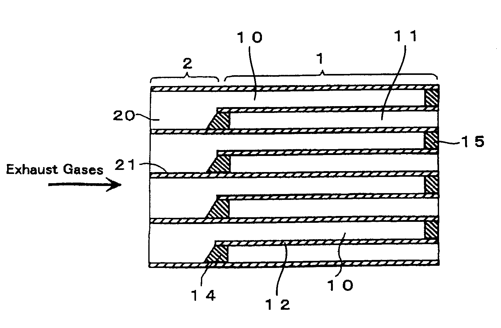
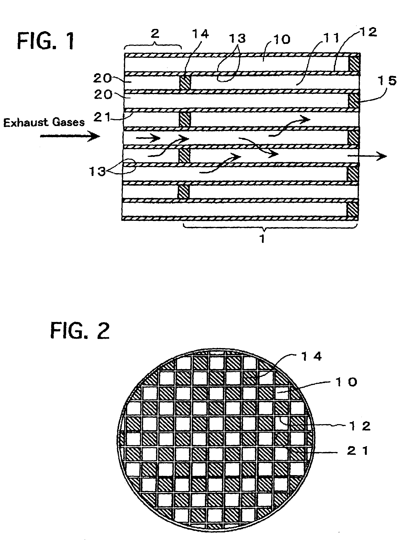
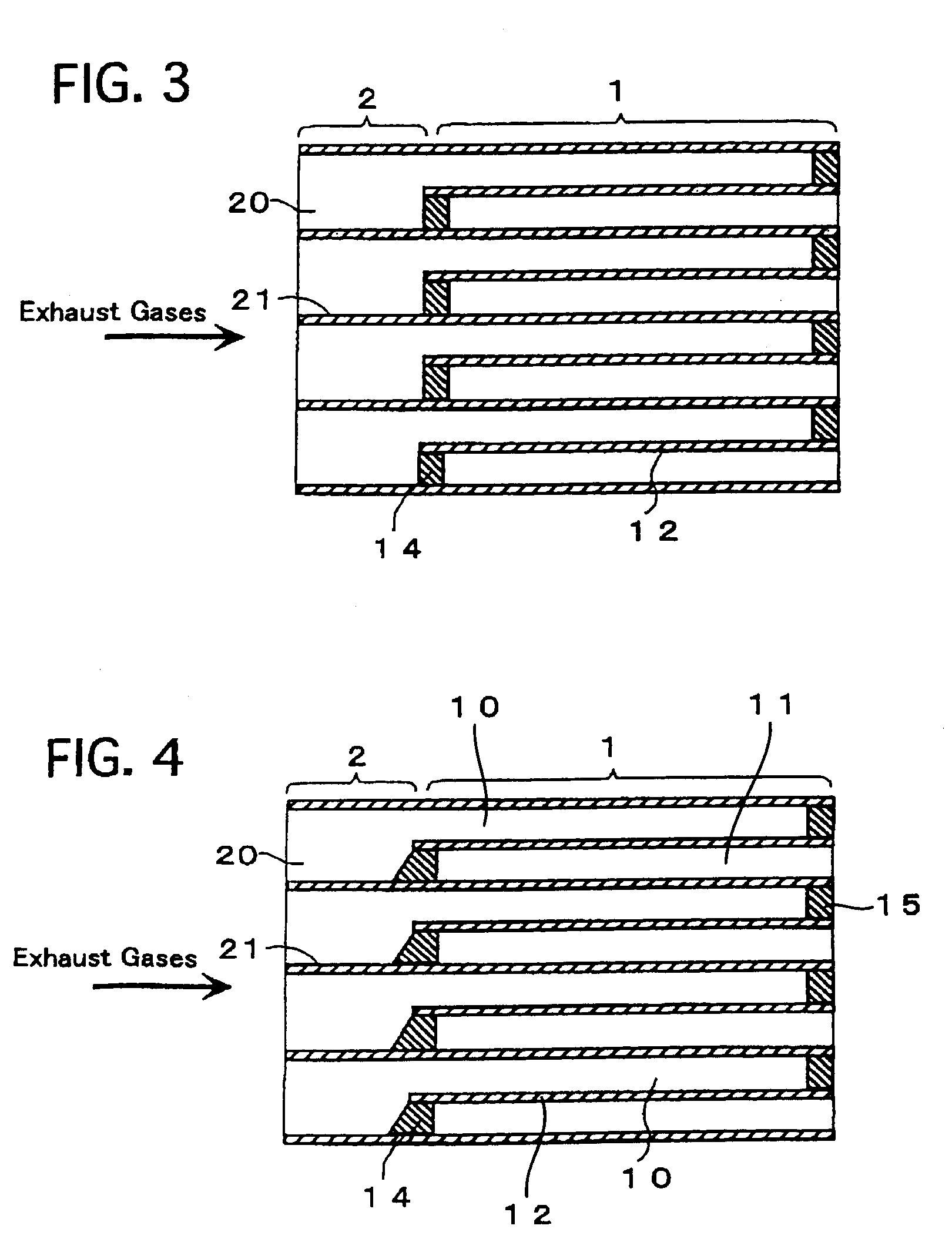
[0067]FIG. 1 illustrates a major cross-sectional view of a filter catalyst for purifying exhaust gases according to Example No. 1 of the present invention. The filter catalyst comprises a wall-flow honeycomb structure 1, and an upstream-side straight-flow honeycomb structure 2. The upstream-side straight-flow honeycomb structure 2 is disposed on an upstream side of exhaust gases with respect to the wall-flow honeycomb structure 1, and is formed integrally with the wall-flow honeycomb structure 1.

[0068]The wall-flow honeycomb structure 1 comprises inlet cells 10, outlet cells 11, filter cellular walls 12, and a catalytic layer 13. The inlet cells 10 are clogged on an downstream side of the exhaust gases. The outlet cells 11 neighbor the inlet cells 10, and are clogged on an upstream side of the exhaust gases. The filter cellular walls 12 demarcate the inlet cells 10 and outlet cells 11. The catalytic layer 13 is formed on the surface of the filter cellular walls 12. More...

example no.2

Example No. 2

[0076]Except that Pt was loaded on the catalytic layers 13 of the upstream-side straight-flow honeycomb structure 2 in an amount of 5 g with respect to 1 L of the upstream-side straight honeycomb structure 2, and that Li, Ba and K were not loaded thereon, a filter catalyst according to Example No. 2 of the present invention had the same arrangements as those of Example No. 1.

[0077]The filter catalyst according to Example No. 2 was improved greatly in terms of the oxidizing activity at the upstream-side straight-flow honeycomb structure 2, compared to Example No. 1. Therefore, it was possible to further improve the warmth-retaining property of the intermediate plugs 14 as well as the warm-up property of the wall-flow honeycomb structure 1.


PUM


Abstract

A filter catalyst is for purifying exhaust gases emitted from internal combustion engines and including particulates, and includes a wall-flow honeycomb structure and an upstream-side straight honeycomb structure. The wall-flow honeycomb structure includes inlet cells clogged on the downstream side of the exhaust gases, outlet cells neighboring the inlet cells and clogged on the upstream side of the exhaust gases, filter cellular walls demarcating the inlet cells and the outlet cells and having pores, and a catalytic layer formed on the surface of the filter cellular walls and/or the surface of the pores of the filter cellular walls. The upstream-side straight honeycomb structure is disposed on the upstream side of the exhaust gases with respect to the wall-flow honeycomb structure, is provided integrally with the wall-flow honeycomb structure, and includes upstream-side straight cells in which the exhaust gases flow straight, and upstream-side cellular walls demarcating the upstream-side straight cells.

Description

BACKGROUND OF THE INVENTION[0001]1. Field of the Invention[0002]The present invention relates to a filter catalyst for purifying exhaust gases, such as those emitted from diesel engines and including particulates.[0003]2. Description of the Related Art[0004]Regarding gasoline engines, harmful components in the exhaust gases have been reduced securely by the strict regulations on the exhaust gases and the technological developments capable of coping with the strict regulations. However, regarding diesel engines, the regulations and the technological developments have been advanced less compared to those of gasoline engines because of the unique circumstances that the harmful components are emitted as particulates (i.e., particulate materials, such as carbonaceous fine particles, sulfuric fine particles like sulfates, and high-molecular weight hydrocarbon fine particles, hereinafter collectively referred to as “PMs”).[0005]As exhaust-gas purifying apparatuses having been developed so ...

Claims


Application Information

Patent Timeline
IPC IPC(8): B01D53/34B01D24/00B01D53/56B01J21/04F01N3/02B01D39/14B01D53/94B01J35/04F01N3/022F01N3/035F01N3/08F01N3/10F01N3/28
CPCB01J35/04F01N3/0222F01N3/035F01N3/0814F01N3/0821F01N3/0842F01N2240/20F01N2330/38F01N2330/48F01N3/021
Inventor OKAWARA, SEIJINISHIMURA, MAMORUISHIHARA, MIKIO
Owner TOYOTA JIDOSHA KK
Why Eureka
Try Eureka