RFID tags

a technology of rfid tags and tags, applied in the field of rfid tags, can solve the problems of impracticality of standoff tags in the majority of commercial applications, inability to read high-frequency rfid tags, and inability to read rfid tags attached to metal containers or soft drinks bottles, etc., and achieve the effect of improving the read distance of tags

Inactive Publication Date: 2007-04-17
LAIRD TECH INC
View PDF4 Cites 53 Cited by
  • Summary
  • Abstract
  • Description
  • Claims
  • Application Information

AI Technical Summary

Benefits of technology

[0014]The present invention overcomes the shortcomings of the prior art. Specifically, the present invention provides a system and method for the use of high frequency RFID tags in conjunction with substrates, particularly metal substrates, as well as substrates used to contain liquid. Briefly, an RFID isolator comprised of a material with complex magnetic permeability, used either by itself, or in combination with dielectric isolator material, is interposed between the RFID tag and the substrate. Alternatively, a material possessing at least two distinct dielectric constants is interposed between the RFID tag and the substrate, such that there is a high dielectric constant at the interface with the substrate, and a low dielectric constant at the interface with the RFID tag. This material can be a single material having a dielectric constant gradient, or alternatively, two or more separate layers, each with a uniform but different dielectric constant, sandwiched together, This material overcomes the inability of many tags to be read on metal substrates using prior art dielectric isolators. In other cases, this material improves the read distance of tags that have limited read distances with prior art dielectric isolators.

Problems solved by technology

Unfortunately, high frequency RFID tags cannot be read when the tag is in close proximity to a metal substrate or a substrate with high water content.
Thus, an RFID tag attached to a metal container or to a bottle containing a soft drink cannot be read, from any distance.
However, standoff tags are impractical in the majority of commercial applications.
The distance between the tag and the article increases the likelihood of the tag being dislodged or damaged in normal use.
However, homogeneous materials with various k values have been tried with little or no success.

Method used


Image

  • RFID tags
  • RFID tags
  • RFID tags

Examples


first embodiment

[0028]FIG. 6 shows the present invention. RFID tag 100 can be specially designed, or purchased from any of a number of companies, such as Intermec Technologies Corporation, Symbol Technologies (formerly Matrics Inc.), Alien Technology, Philips Semiconductor, and Texas Instruments. In the preferred embodiment, the RFID tag operates in the frequency range between 800 and 1000 MHz, with the most preferably center frequencies being 869 MHz, 915 MHz and 953 MHz. This RFID tag can be self-powered by inclusion of a power source, such as a battery. Alternatively, it can be field-powered, such that it generates its internal power by capturing the energy of the electromagnetic waves being transmitted by the base station and converting that energy into a DC voltage.

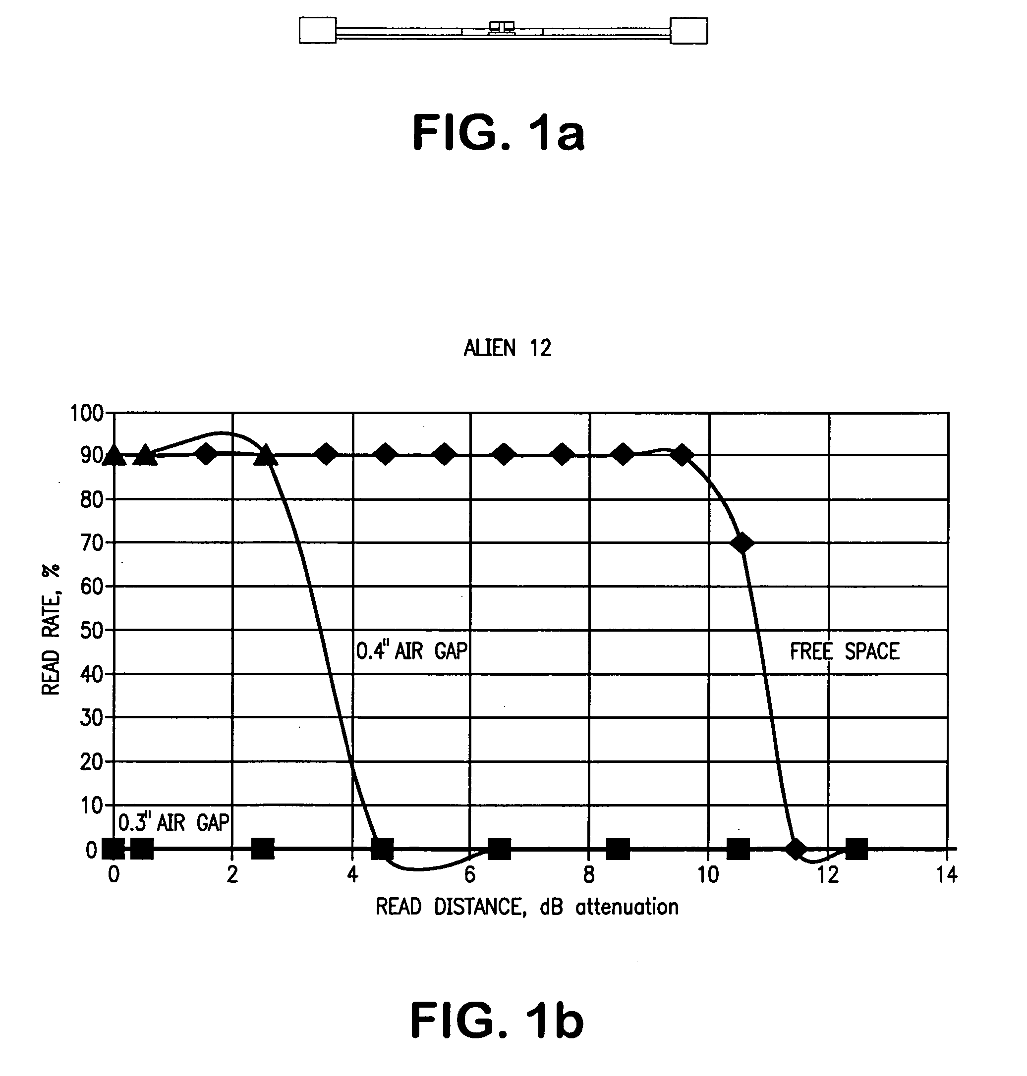
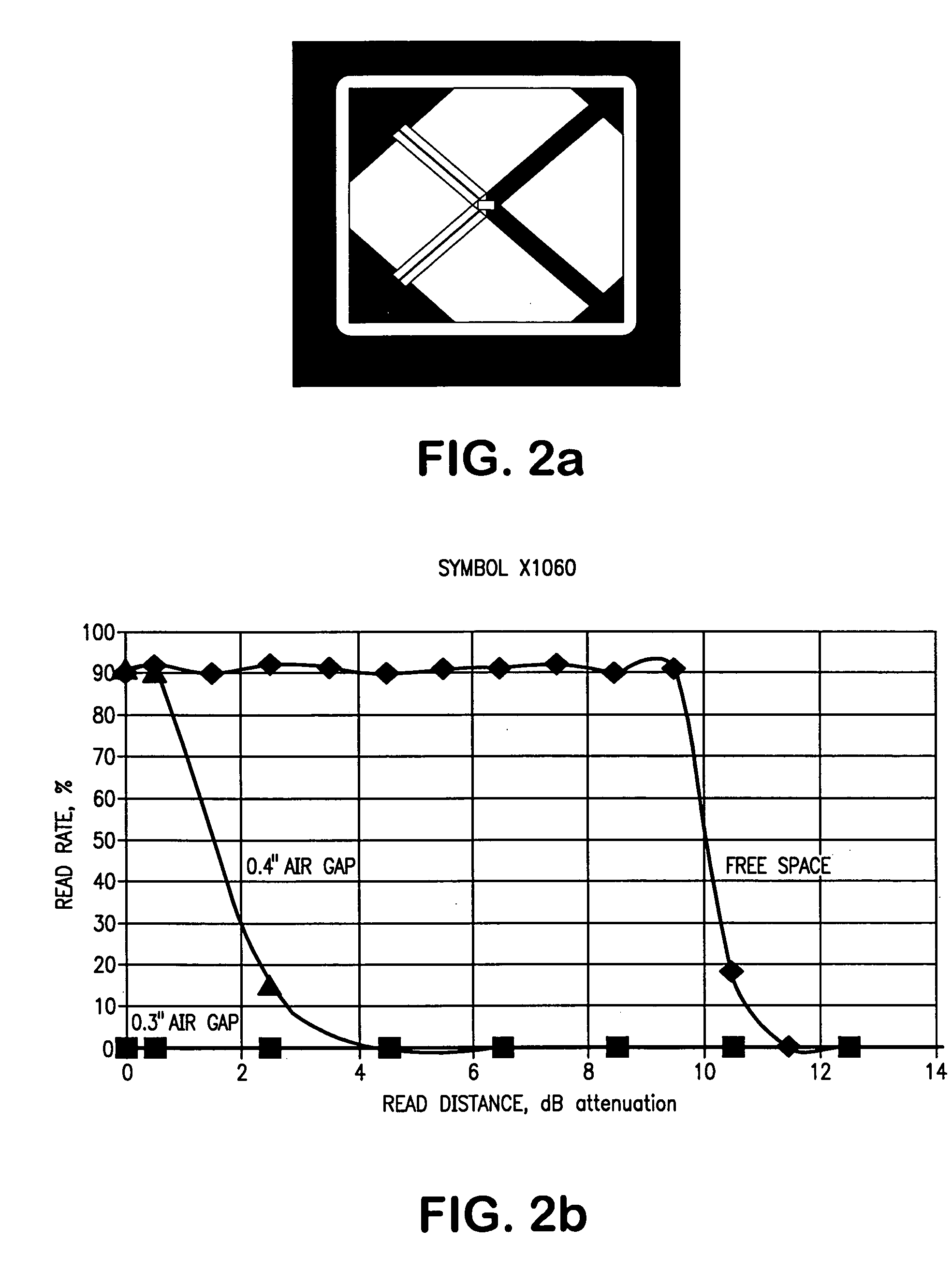
[0029]Article 110 is the object to be tagged. As described above, articles comprising a metal substrate, or configured to contain liquid are problematic, with respect to read distances. In various testing, a tag could not be read wh...

third embodiment

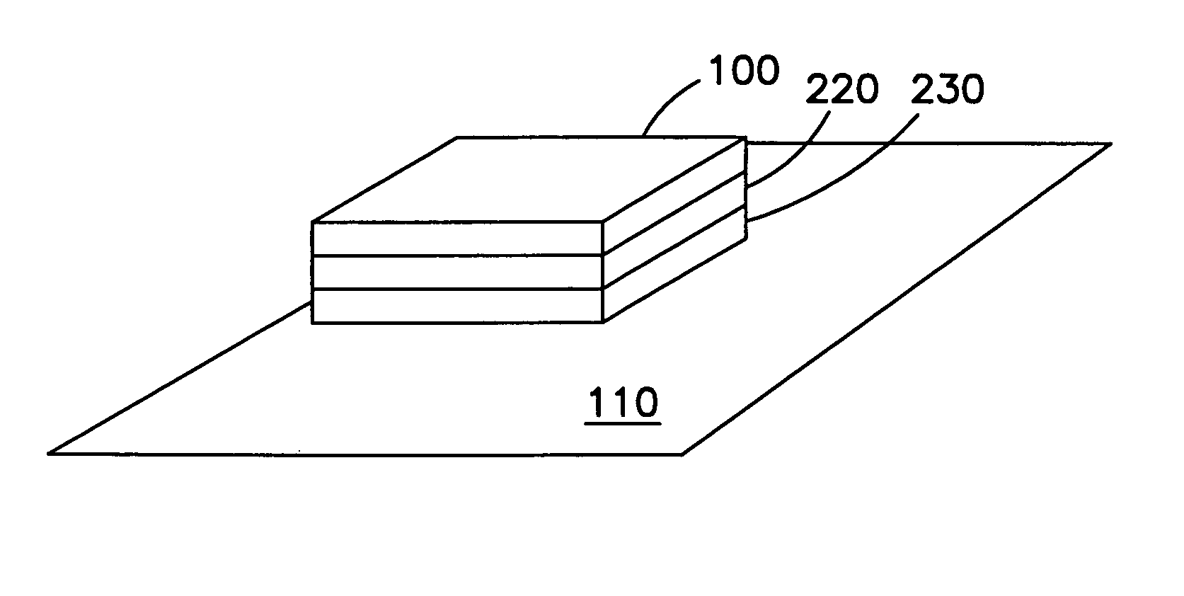
[0072]FIG. 8 shows the present invention. While the previous two embodiments utilized existing RFID tags, FIG. 8 combines these existing RFID tags with the present invention to create an integral solution.

[0073]Integrated Circuit 300 is affixed to the top surface of substrate 320, such as by soldering or gluing. This integrated circuit preferably contains the identifying information related to the article. Substrate 320 typically consists of a printed circuit board, although other substrates are possible. In most RFID tags, the antenna 310 is affixed directly to the substrate 320. In many applications, the antenna 310 is created by printing specially sized and spaced wire etches directly on the substrate 320. Those skilled in the art are familiar with various processes of embedding antennas into printed circuit boards.

[0074]Affixed to the opposite surface of substrate 320 is a layer of material 330. In one embodiment, the layer of dielectric gradient material described with respect ...


PUM

PropertyMeasurementUnit
dielectric constantaaaaaaaaaa

Abstract

A system and method for the use of ultra high frequency RFID tags in conjunction with metal substrates, as well as substrates used to contain liquid. Briefly, an RFID isolator comprised of a material with complex magnetic permeability, used either by itself, or in combination with dielectric isolator material, is interposed between the RFID tag and the substrate. Alternatively, a material possessing at least two distinct dielectric constants is interposed between the RFID tag and the substrate, such that there is a high dielectric constant at the interface with the substrate, and a low dielectric constant at the interface with the RFID tag. This material can be a single material having a dielectric constant gradient, or alternatively, two or more separate layers, each with a uniform but different dielectric constant, sandwiched together.

Description

[0001]This application claims priority of U.S. Provisional Application Ser. No. 60 / 615,826, filed Oct. 4, 2004, and U.S. Provisional Application Ser. No. 60 / 713,861, filed Sep. 2, 2005, the disclosures of which are incorporated herein by reference.BACKGROUND OF THE INVENTION[0002]Radio Frequency Identifier (RFID) tags are used in a variety of applications, such as inventory control and security. Unlike barcode tracking systems, the advantage of these more intelligent RFID systems is that an RFID system can store specific information about an article and can read that information on a tag without requiring line of sight or a particular orientation. This means that RFID systems can be largely automated, reducing the need for manual scanning.[0003]These RFID tags are typically placed on or in articles, or containers such as cardboard boxes. The RFID tags work in conjunction with an RFID base station. The base station supplies an electromagnetic wave output, which acts as the carrier fr...

Claims


Application Information

Patent Timeline
Patent Type & Authority Patents(United States)
IPC IPC(8): G08B13/14
CPCG06K19/07749G06K19/07771
Inventor DIXON, PAUL F.CARPENTER, MICHAEL P.OSWARD, MARY M.GIBBS, DAVID A.
Owner LAIRD TECH INC
Why Eureka
Try Eureka