Air saw

a technology of air saw and air frame, which is applied in the direction of saw chains, non-mechanical valves, servomotors, etc., can solve the problems of increasing noise, reducing durability, and further liable to generate chatter, so as to improve durability, prevent chattering, and improve work efficiency.

Inactive Publication Date: 2007-04-24
KUKEN
View PDF15 Cites 14 Cited by
  • Summary
  • Abstract
  • Description
  • Claims
  • Application Information

AI Technical Summary

Benefits of technology

[0019]During the operation of the air saw, when the saw blade is caught on an object to be worked and the operator pulls the air saw so as to break this up, if the main spindle further advances across the normal advanced position, the front air-cushion chamber is sealed. Thus, due to the air pressure in the sealed front air-cushion chamber and the elastic force of the front return-spring, the front plate is pushed rearward, so that the abnormal advancement of the main spindle is blocked, preventing the chattering.
[0020]Therefore, the breakdown of part of the main spindle due to the chattering is prevented, improving the durability while the part fixing the saw blade is prevented from loosening or allowing the saw blade to come off because of the vibration due to the chattering. Thus, the work efficiency can be greatly improved.
[0021]Moreover, the chattering can be prevented, so that a conventional large amount of noise and vibration can be reduced, improving the work environment and the worker's health.
[0022]In addition to these, ends of the front and rear air-cushion chambers communicate with the atmospherically opened exhaust path while a flow-regulating valve is provided in the exhaust path so as to adjust the stroke of the saw blade by the flow regulation with the flow-regulating valve. Therefore, only the external side of the member to be cut having a double structure can be cut, for example, further improving the work efficiency.

Problems solved by technology

The chattering is further liable to be generated when the supplied air pressure is increased.
There has also been a problem that part of the main spindle 129 attaching the back plate 130 is liable to break, reducing durability.
Furthermore, the chattering not only causes increased noise, but also increases the vibration, thereby deteriorating the work environment and the worker's health.
However, the force driving the main spindle is extremely reduced because of reduced energy supply, which is not fit for practical use.

Method used


Image

  • Air saw
  • Air saw
  • Air saw

Examples


Embodiment Construction

[0037]An air saw according to an embodiment of the present invention will be described below with reference to the drawings.

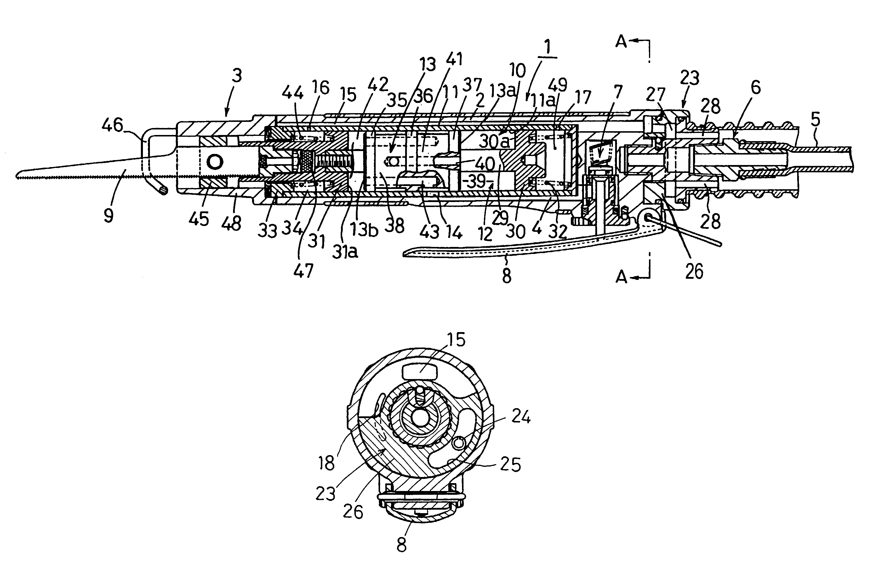
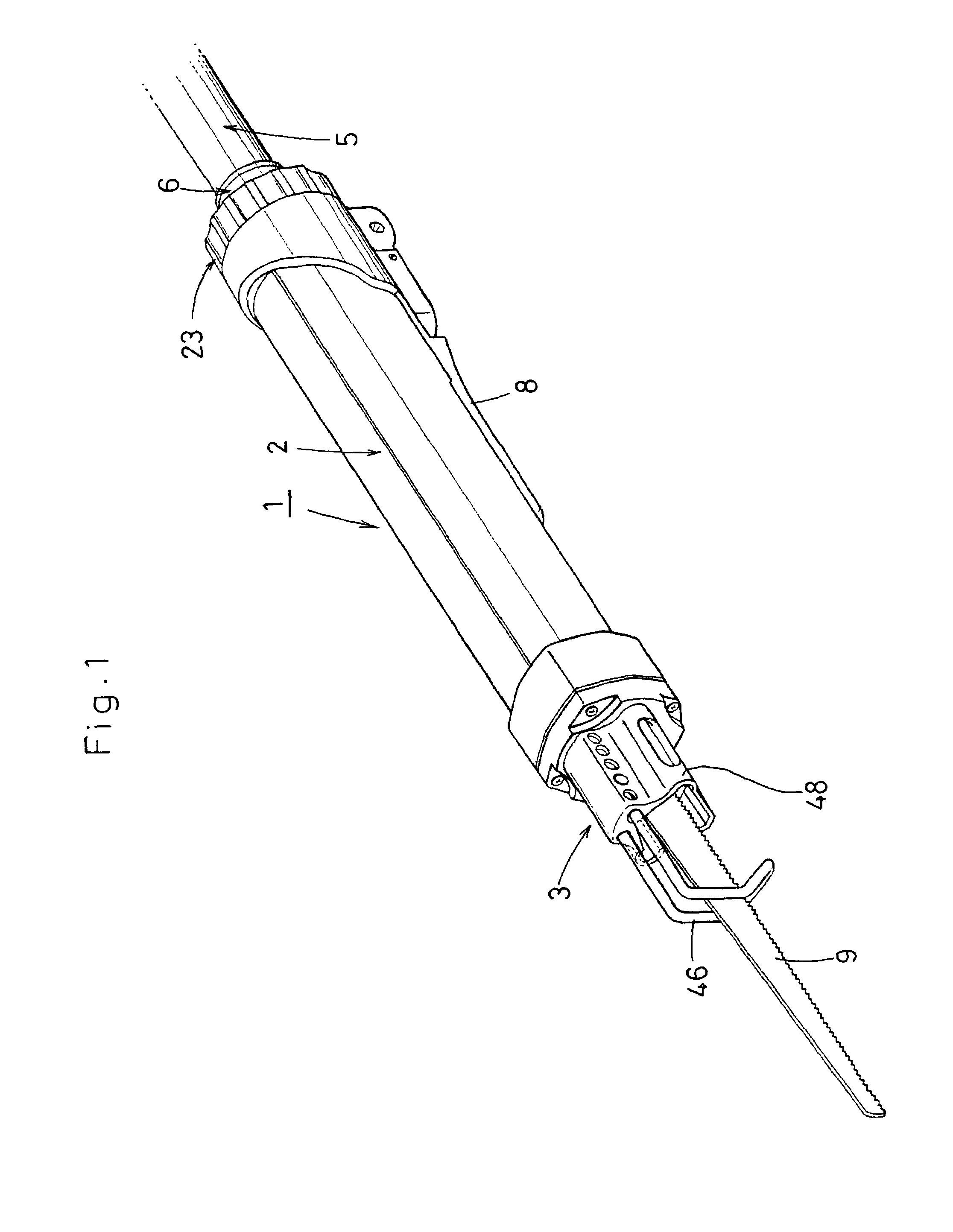
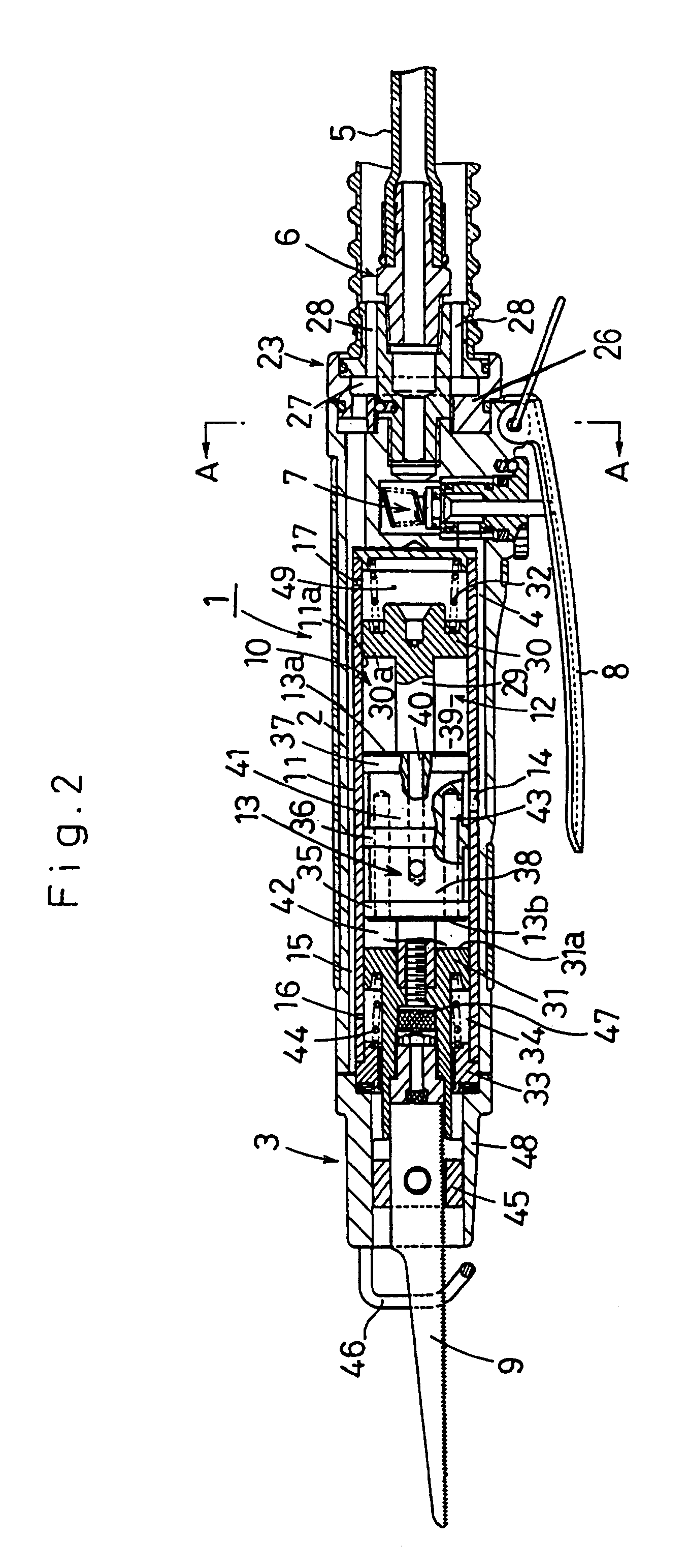
[0038]FIG. 1 is a perspective view of the air saw and the entire air saw is indicated by numeral 1. The air saw 1 comprises a substantially cylindrical casing 2, a blade-connection part 3 arranged in the front of the casing 2, and a hose-connection part 6 disposed at the rear end of the casing 2 to be connected to a hose 5 for supplying the air pressurized by a compressor (not shown) to an air-supply path 4. On the rear bottom surface of the casing 2, an operating lever 8 is provided for supplying the air supplied to the hose-connection part 6 to the air-supply path 4 by operating an on-off valve 7 interposed in the air-supply path 4 (see FIG. 2).

[0039]The casing 2 is provided with a blade driver 10 assembled therein for reciprocating a saw blade 9 attached to the blade-connection part 3 by operation of the operating lever 8 with the air supplied from the hose-...


PUM

PropertyMeasurementUnit
pressureaaaaaaaaaa
internal pressureaaaaaaaaaa
strengthaaaaaaaaaa

Abstract

A main spindle of an air saw is reciprocated by sliding a piston in a cylinder chamber with the pressure of air supplied to the cylinder chamber via an air supply path so as to alternately apply the air pressure to pressure-receiving surfaces of a back plate and a front plate, wherein a rear air-cushion chamber is formed in a portion for fixing a return spring for urging the back plate toward the center of a cylinder while a front air-cushion chamber is formed in a portion for fixing a return spring for urging the front plate toward the center of the cylinder, so that the front and rear balance is maintained.

Description

BACKGROUND OF THE INVENTION[0001]1. Field of the Invention[0002]The present invention relates to an improvement in an air saw used for plate cutting work and deburring of metallic products as a kind of air tool.[0003]2. Description of the Related Art[0004]As shown in FIGS. 9 and 10, a general structure of an air saw 101 includes: a piston 113 slidably accommodated in a cylindrical cylinder chamber 112 arranged in a saw casing 102; a main spindle 129 passing through the piston 113 and having a back plate 130 arranged toward the rear end and a front plate 131 arranged toward the front end; and a blade-applied part 103 arranged at the front end of the main spindle 129 for attaching a saw blade 109 thereto.[0005]Return springs 132 and 144 are respectively arranged in return-spring chambers 150 and 151, which are provided at the rear of the back plate 130 and the front of the front plate 131, respectively. Due to the return springs 132 and 144, the back plate 130 and the front plate 131 ...

Claims


Application Information

Patent Timeline
Patent Type & Authority Patents(United States)
IPC IPC(8): B23D49/10B23D49/16B26D5/04B27B19/04B27B19/09B23D51/18F15B11/06F15B15/00F15B15/22
CPCB23D51/18Y10T83/929
Inventor NAKAMURA, AKINORI
Owner KUKEN
Why Eureka
Try Eureka