
Spray coating apparatus and fixtures

a coating apparatus and fixture technology, applied in the direction of liquid surface applicators, semiconductor/solid-state device details, coatings, etc., can solve the problems of high cost associated with these types of devices, parts are usually reworked rather than disposed, and limit their throughput, so as to achieve the effect of limited throughput and high cos

Inactive Publication Date: 2007-04-24
MICROSEMI CORP MEMORY & STORAGE SOLUTIONS
View PDF12 Cites 14 Cited by
  • Summary
  • Abstract
  • Description
  • Claims
  • Application Information

AI Technical Summary

Benefits of technology

[0018]Repeatability and reliability of applying a TRC to parts is extremely important for processing multi-chip modues (MCMs) containing expensive ASICs (Application Specific Integrated Circuits). These modules are highly compact circuits having the functionality of several integrated circuits or a printed circuit board. Because of the high cost associated with these types of devices, parts are usually reworked rather than disposed of when found to be defective. This has conventionally limited their throughput due to the need to process these devices correctly the first time through. The features of the present invention enable more expensive types of MCMs to be coated in large batches that consistently meet quality control standards without requiring substantial reworking of parts.
[0019]Furthermore, a spray wheel of the present invention is configured for quick loading and unloading of device fixtures without requiring threaded fasteners or lock pins.
[0021]Another aspect of the present invention includes a spray wheel having a spray surface free of all screws, bolts and other design features that may trap sprayed coating material to promote simpler removal of unwanted over-spray.
[0023]Another aspect of the present invention is to provide a wheel-based spray coating system including a fixture mounting system for simplified addition / removal of device-holding fixtures to and from the wheel.

Problems solved by technology

Because of the high cost associated with these types of devices, parts are usually reworked rather than disposed of when found to be defective.
This has conventionally limited their throughput due to the need to process these devices correctly the first time through.

Method used


Image

  • Spray coating apparatus and fixtures
  • Spray coating apparatus and fixtures
  • Spray coating apparatus and fixtures

Examples


Embodiment Construction

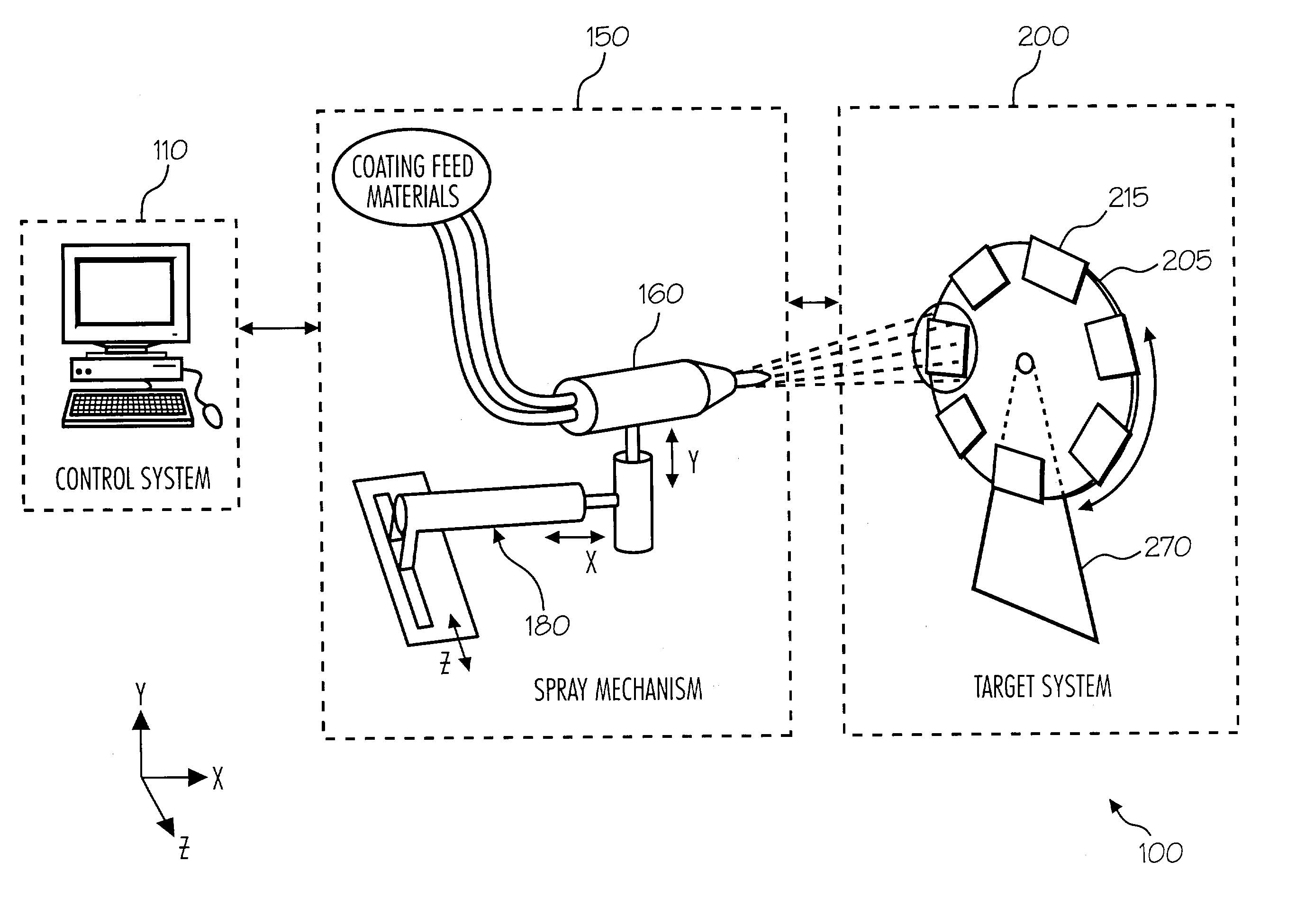
[0034]Turning to FIG. 3A, a coating system 100 for spray coating parts, according to one aspect of the invention includes a spray coating control system 110, a spray coating mechanism 150, and a spray target system 200.

[0035]Spray mechanism 150 functions to spray a coating material towards target system 200 to coat one or more devices with a coating. Spray mechanism 150 may be any device or combination of device for accomplishing this function. In preferred embodiments of the present invention, spray mechanism 150 comprises a thermal spray gun 160 similar to that disclosed by Heffner et al., and a spray gun mounting system 180. However, there is nothing herein that limits the present invention to thermal spray processes.

[0036]In the most preferred embodiments of the present invention, unlike the thermal spray system disclosed by Heffner et al., mounting system 180 is configured to be able to electrically, mechanically, and / or hydraulically move gun 160 in one or more directions. As ...


PUM


Abstract

A system for applying a sprayed coating includes a spray mechanism operative to spray a liquefied coating material; a target system including a rotatable spray target wheel; and one or more device-holding fixtures configured to be mounted onto the spray target wheel without requiring either an unattached threaded fastener or a locking pin. Preferred embodiments of the system are configured for thermal spray application of Tamper Resistant Coatings (TRCs).

Description

BACKGROUND OF THE INVENTION[0001]1. Technical Field[0002]The present invention is related to devices and fixtures for coating objects with a sprayed material. More particularly, but no exclusively, the invention relates to devices and methods for thermal spray processes.[0003]2. Background Art[0004]There are many applications in which it is desired to apply a coating to a part or form a product layer using a spray process. Such applications may include applying primers, paints, and / or other types of coatings. Once such coating for which the present invention may used, but is not limited to, is the application of a tamper resistant coating (TRC). A TRC is a layer applied to a product to provide a physical barrier to prevent inspection of, and tampering with, for example, the underlying circuitry and contents of electronic components.[0005]Processes and systems for coating electronic circuits with protective coatings and security coatings using a thermal spray are generally known. Exa...

Claims


Application Information

Patent Timeline
Patent Type & Authority Patents(United States)
IPC IPC(8): B05C5/00B05B7/20B05B13/02H01L21/00H01L21/56H01L23/58
CPCB05B13/0242H01L21/56H01L21/6715H01L23/585B05B7/20H01L2924/0002H01L2924/00
Inventor ANDERSON, CURTIS WAYNEREEVES, LENARDHEGGLI, BJARNEDOWLAND, JR., THOMAS WILLIAM
Owner MICROSEMI CORP MEMORY & STORAGE SOLUTIONS
Learn More