Liquid crystal projector

a liquid crystal projector and projector technology, applied in the field of display devices, can solve the problems of deteriorating video signals, noise or problems of emi or emc, and restrictions on circuit board design, and achieve the effect of suppressing nois

Inactive Publication Date: 2007-04-24
PANASONIC LIQUID CRYSTAL DISPLAY CO LTD +1
View PDF15 Cites 20 Cited by
  • Summary
  • Abstract
  • Description
  • Claims
  • Application Information

AI Technical Summary

Benefits of technology

[0010]In order to equalize lengths of signal lines to plural liquid crystal display panels, respectively, a circuit for increasing a frame frequency and a liquid-crystal-panel drive control circuit for controlling the liquid crystal panel are disposed on a separate circuit board to be independent from other circuits, and the circuit board is provided for each liquid crystal panel, and connected to it with a flexible cable, thus supplying small-amplitude video signals of the differential-mode. With such an arrangement, it is possible to suppress the problems of noise, EMI or EMC since slow-signal lines can be used to connect the other circuits with the circuit for increasing a frame frequency.

Problems solved by technology

However, it was found that the increased frame frequency caused problems with electromagnetic interference (EMI) and electromagnetic compatibility (EMC), and thus causing some restrictions on designing the circuit board.
More specifically, since the liquid crystal panel is disposed to fit the shape of optical system of a projector comprising a plurality of liquid crystal panels, the length of signal wiring to the liquid crystal panels from the circuit for increasing the frame frequency becomes longer, thus causing noise or problems with EMI or EMC.
This revealed a problem that the higher-frequency signal deteriorates video signals due to the wiring loading effects.
This also causes another problem that it is difficult to equalize lengths of signal lines to three liquid crystal display panels associated with three primary colors, respectively.

Method used


Image

  • Liquid crystal projector
  • Liquid crystal projector
  • Liquid crystal projector

Examples


Embodiment Construction

[0071]Hereinafter, preferred embodiments of the present invention will be described in detail with reference to the drawings. It should be noted that, in all figures for describing the preferred embodiments of the present invention, components having the same are denoted by like numerals, and the duplicated descriptions thereof are omitted.

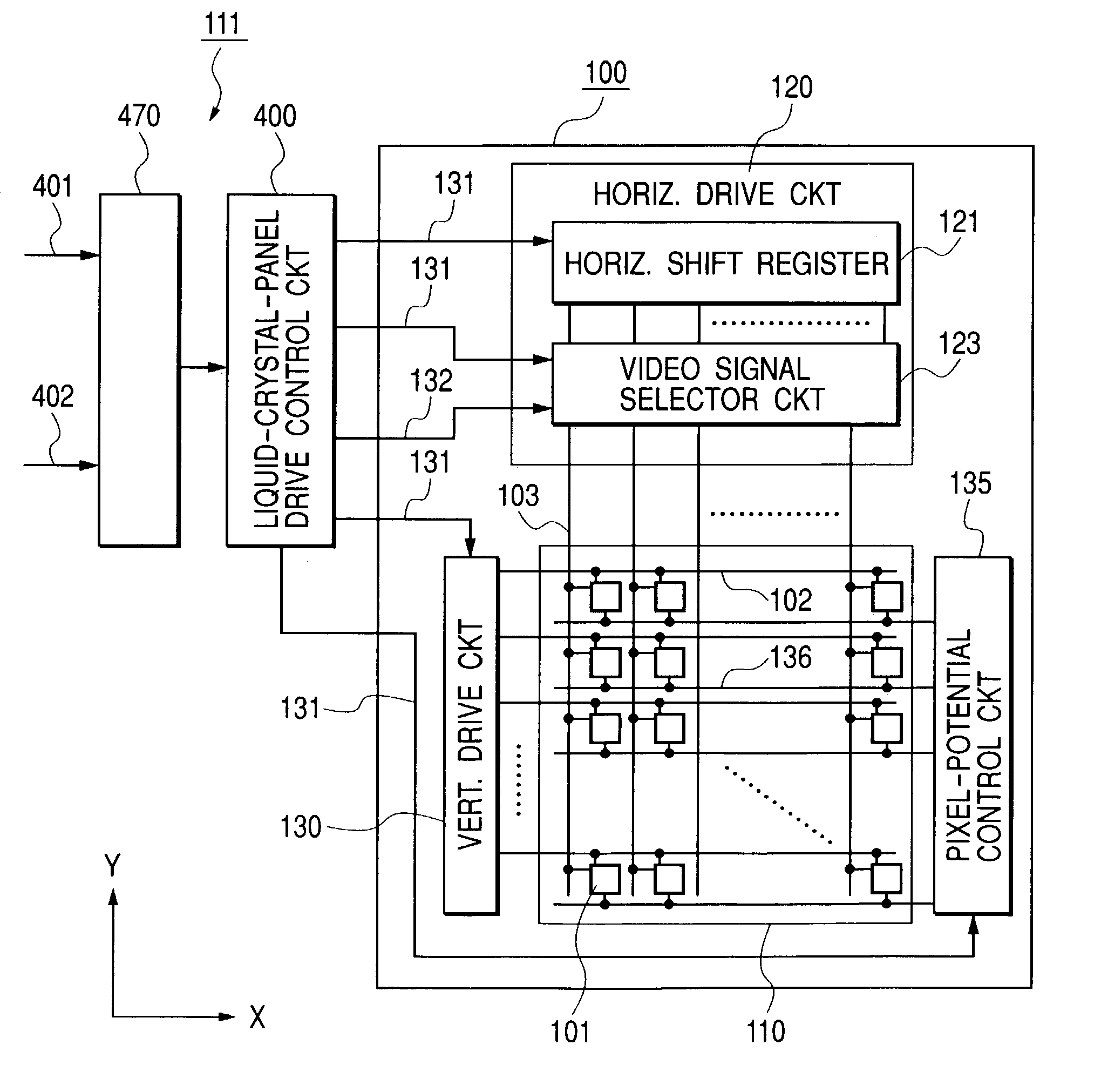
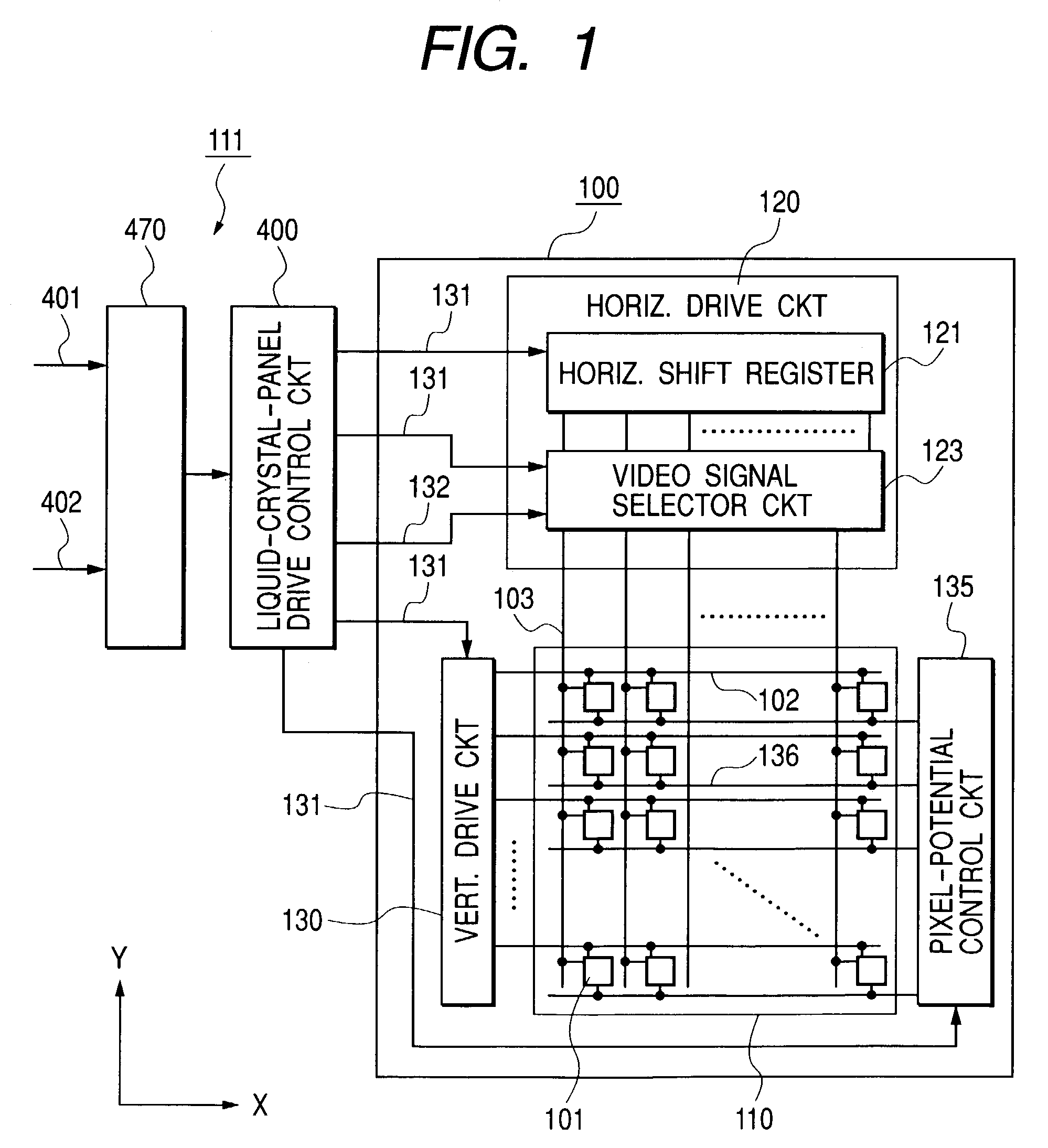
[0072]FIG. 1 is a block diagram showing a schematic configuration of a crystal display device according to a preferred embodiment of the present invention.

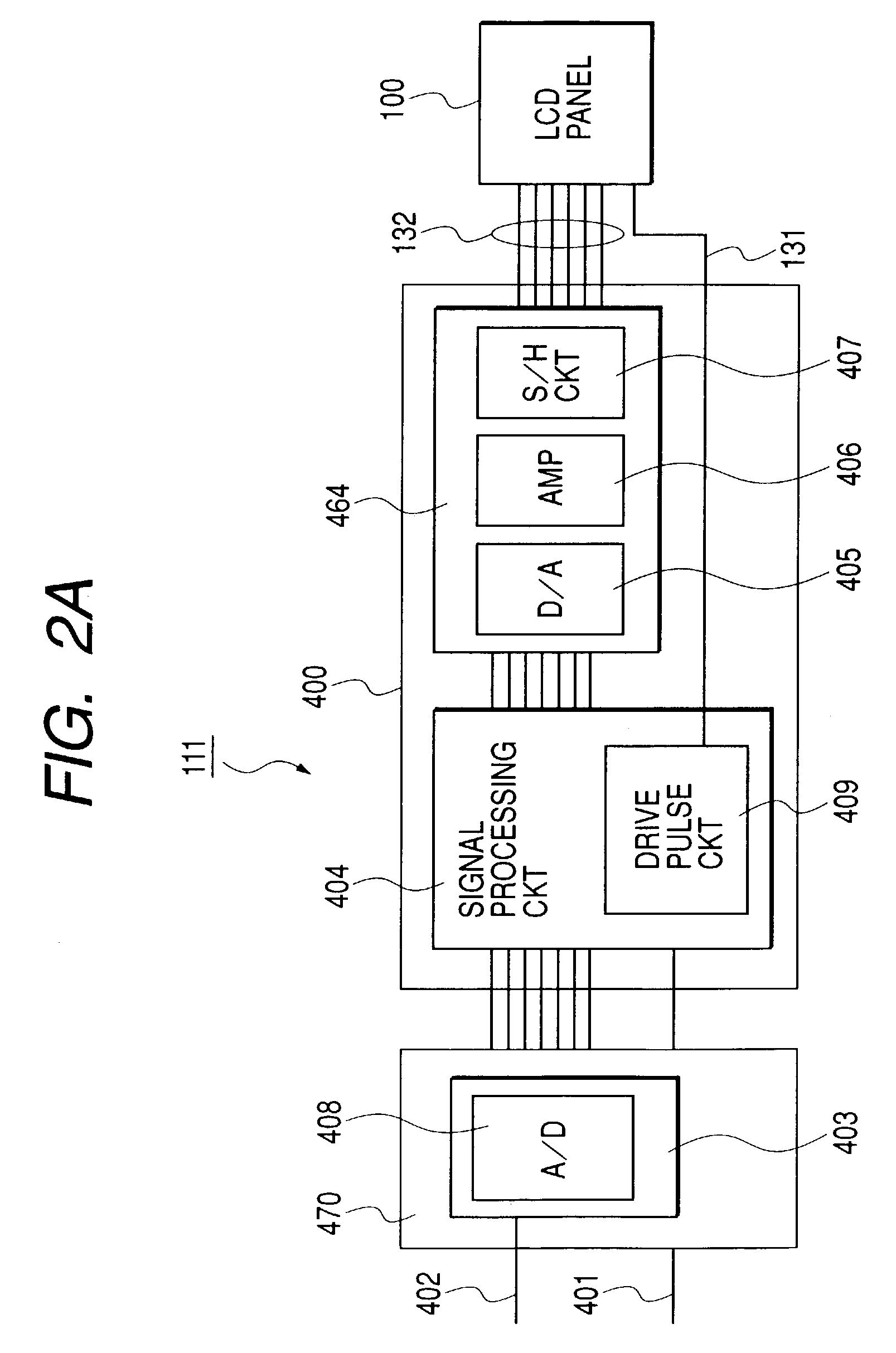
[0073]The crystal display device according to the preferred embodiment of the present invention includes a liquid crystal panel (liquid crystal display element) 100 and a display control device 111. The display control device 111 is divided into a liquid crystal panel control circuit 400 and a preprocessor circuit 470.

[0074]The liquid crystal panel 100 includes a display section 110 where a pixel section 101 is disposed in a matrix arrangement, a horizontal drive circuit (video signal line drive...


PUM

PropertyMeasurementUnit
frame frequencyaaaaaaaaaa

Abstract

A projector includes a liquid crystal display device has a liquid crystal display panel and a display control device coupled to the liquid crystal display panel. The display control device is composed of a first section for receiving an externally supplied video signal, and a second section succeeding the first section and coupled to the liquid crystal display panel. The second section is formed of a circuit for amplifying and converting the video signal into an ac signal supplied from the first section, and a drive pulse circuit for outputting drive pulses for driving the liquid crystal display panel. The first section and the second section are fabricated on first and second substrates separate from each other, respectively. The second section is disposed proximately to the liquid crystal display panel, and the first section and the second section are coupled via a flexible cable.

Description

BACKGROUND OF THE INVENTION[0001]The present invention relates to a display device, and more particularly to a technology that can be effectively applied to a liquid-crystal-panel drive circuit configuration in a liquid crystal display device incorporating plural display elements which receive higher frequency video signals.[0002]In recent years, liquid crystal display devices have been rapidly increased in popularity of their use ranging from small display devices to display terminals such as office automation equipment. Basically, the liquid crystal display device is so configured to form a liquid crystal panel (also referred to as a liquid display element or a liquid crystal cell) which has a layer of liquid crystal composition (a liquid crystal layer) sandwiched between a pair of insulating substrates, at least one substrate of which is made of a transparent glass plate or a transparent plastic substrate.[0003]The liquid crystal panel produces an image by selectively applying vo...

Claims


Application Information

Patent Timeline
Patent Type & Authority Patents(United States)
IPC IPC(8): G09G3/36G02F1/13G02F1/133G02F1/1345G06F3/14G09F9/00G09F9/30G09F9/35G09G3/20G09G5/00H04N9/31
CPCG06F3/14G09G3/3648G09G5/006H04N9/3197H04N9/3105G09G3/3611G09G2300/0876G09G2320/0285G09G2320/0626G09G2320/066G09G2320/0673G09G2330/06G09G2340/04G09G2320/0606G09G3/36
Inventor MAEDA, TOSHIOWATANABE, AKIHIROMARUOKA, YOSHIOMISONOU, TOSHIKINAKAGAWA, HIDEKI
Owner PANASONIC LIQUID CRYSTAL DISPLAY CO LTD
Why Eureka
Try Eureka