Optical clock recovery device for recovering the clock from an optical signal

a clock recovery and optical clock technology, applied in the field of optical telecommunications, can solve the problems of inability to eliminate jitter, less effective regeneration device, and inability to recover clocks from optical signals, and achieve the effect of improving the stability of amplitude and frequency

Active Publication Date: 2007-04-24
ALCATEL LUCENT SAS
View PDF4 Cites 13 Cited by
  • Summary
  • Abstract
  • Description
  • Claims
  • Application Information

AI Technical Summary

Benefits of technology

[0026]Accordingly, unlike the received signal, the clock signal runs no risk of including long periods with no pulses. As a result of this the second clock recovery device supplies a second clock signal with improved stability of amplitude and frequency.

Problems solved by technology

Thus clock recovery must be effected at the rhythm of the received packets, which implies constraints on the acquisition and holding time of the clock recovery devices.
However, injecting a signal at a sufficient power level into the device gives rise to another problem due to a phenomenon called the patterning effect.
This amplitude modulation and jitter make the regenerator devices less effective.
The amplitude modulation of the clock signal could be eliminated by means of an all-optical equalizer device of a type known in the art, but an all-optical equalizer device is incapable of eliminating the jitter.

Method used


Image

  • Optical clock recovery device for recovering the clock from an optical signal
  • Optical clock recovery device for recovering the clock from an optical signal
  • Optical clock recovery device for recovering the clock from an optical signal

Examples


Embodiment Construction

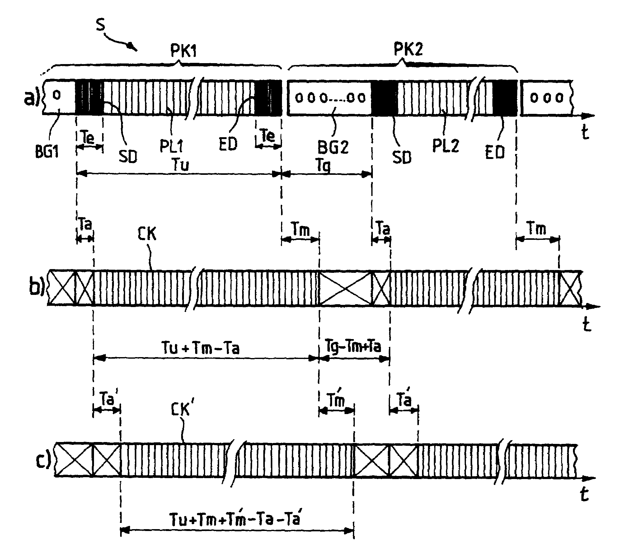
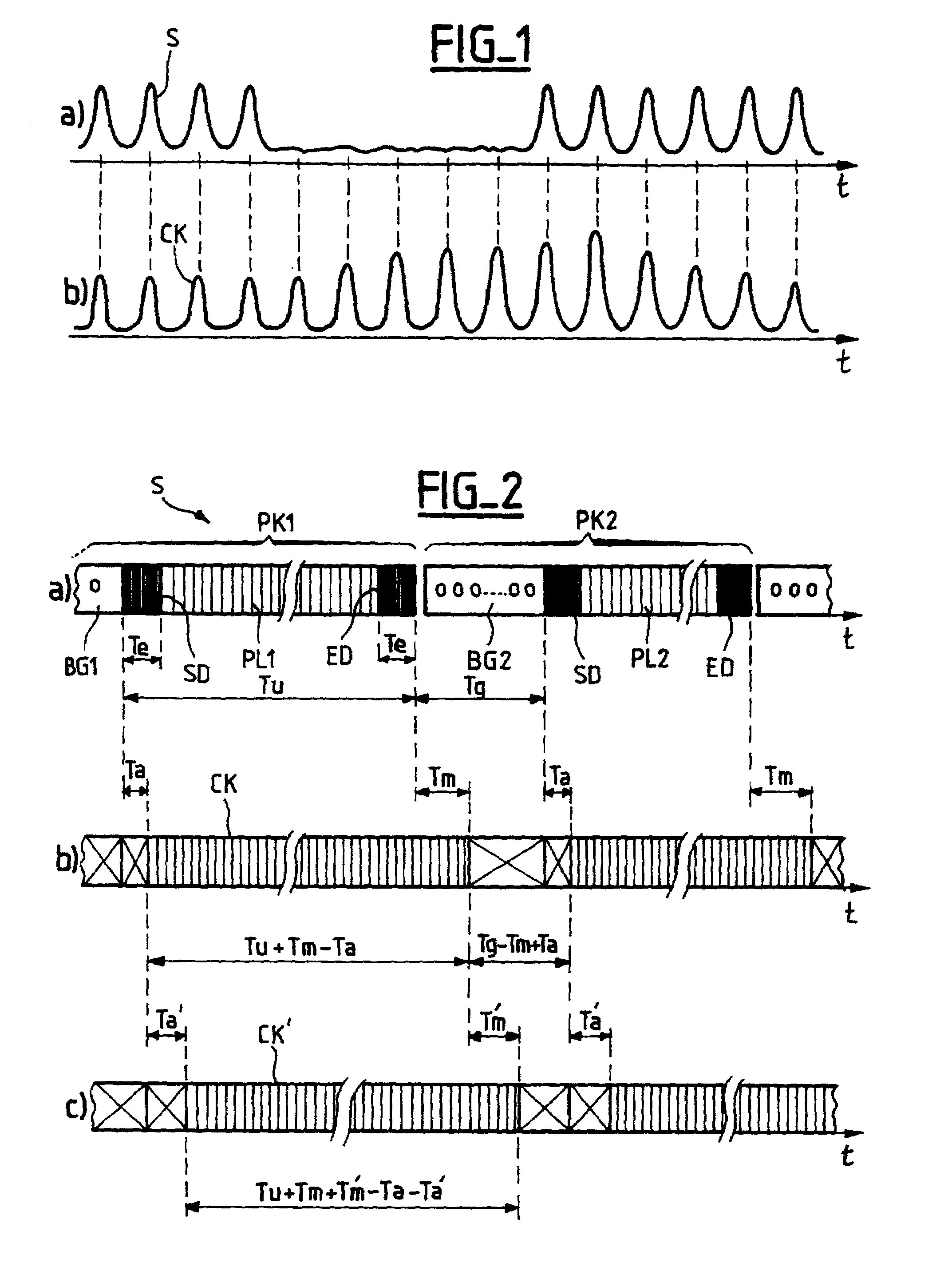
[0036]The FIG. 2 timing diagrams represent the main signals operative in a clock recovery system according to the invention.

[0037]As shown in timing diagram a), the received signal S comprises successive packets PK1, PK2 each comprising a guard band BG1, BG2 followed by a payload PL1, PL2 containing the information data of the packet. The guard band has a transmission time Tg, called the guard time, during which the optical power is low. The existence of this guard time guarantees a predefined minimum time-delay between the reception of two successive payloads. The transmission time Tu of the payload of each packet is a function of the number of bits in the payload and the bit rate.

[0038]The payload includes a preamble SD at the start, followed by an information field, and finally an end pattern ED. The preamble and the end pattern comprise predefined sequences of successive “1” bits with a corresponding transmission time Te.

[0039]The timing diagram b) of FIG. 2 shows a first clock ...


PUM


Abstract

An all-optical clock recovery system for recovering the clock from a received optical signal with a short response time and without patterning effects includes a first optical clock recovery device adapted to supply a first optical clock signal in response to the received optical signal and a second optical clock recovery device adapted to supply a second optical clock signal in response to the first optical clock signal. Applications include regenerating optical packets in asynchronous optical packet-switched telecommunication networks.

Description

CROSS REFERENCE TO RELATED APPLICATIONS[0001]This application is based on French Patent Application No. 01 06 519 filed May 17, 2001, the disclosure of which is hereby incorporated by reference thereto in its entirety, and the priority of which is hereby claimed under 35 U.S.C. §119.BACKGROUND OF THE INVENTION[0002]1. Field of the Invention[0003]The invention relates to optical telecommunications and in particular to transmission systems in which binary optical signals are conveyed in the form of amplitude modulation of a carrier wave, the modulation is synchronized by a clock and the signals are organized into packets of binary information.[0004]The invention relates to the problem of recovering from a received binary optical signal a clock signal comprising a stream of pulses having a stable recurrence frequency equal to that of the clock bit rhythm of the received signal.[0005]2. Description of the Prior Art[0006]Clock recovery is of particular benefit in regenerator devices for ...

Claims


Application Information

Patent Timeline
Patent Type & Authority Patents(United States)
IPC IPC(8): H04B10/00H01S3/10H04B10/508H04B10/524H04B10/54H04B10/556H04L7/00
CPCH04L7/0075
Inventor CHIARONI, DOMINIQUELAVIGNE, BRUNODEVAUX, FABRICESARTORIUS, BERNDBORNHOLDT, CARSTENBAUER, STEPHAN
Owner ALCATEL LUCENT SAS
Why Eureka
Try Eureka