Refrigerator

a vacuum heat insulation and refrigerator technology, applied in the field of heat insulation boxes, can solve the problems of difficult practical use, unavoidable energy saving in electric appliances, and disclosure of vacuum heat insulation devices

Inactive Publication Date: 2007-05-01
PANASONIC CORP
View PDF39 Cites 66 Cited by
  • Summary
  • Abstract
  • Description
  • Claims
  • Application Information

AI Technical Summary

Problems solved by technology

Energy saving in electric appliances is an unavoidable important problem that has been addressed in recent years.
However, these conventional techniques have following problems and thus are difficult to be put to practical use.
For example, the vacuum heat insulator disclosed in Japanese Patent Examined Publication No. 30-3139 is difficult to be formed into a specific shape because it is made of glass fibers only.
When a sheet-form vacuum heat insulator is to be produced, using glass fibers as a core of the vacuum heat insulator requires much manpower because the fibers themselves do not have shape-keeping properties.
However, as general methods cannot be used to sew the fibers, while reducing heat conduction, this process has a problem of high production costs.
However, this publication only discloses a type of the binder and does not disclose an amount of the binder or a composition of the fibers.
Thus, there is a problem in that it is difficult to bind fibers together using the binder while maintaining heat insulating properties suitable for a vacuum heat insulator.
In addition, when organic fibers are used for a core, the core generates gases during a long-term usage, and thus, heat insulating properties may be degraded.
Such a core has a problem of long-term heat insulating properties or workability.
As described above, conventional techniques have problems such as poor workability of the vacuum heat insulator, or a premature stage of product development, and advantages of fiber aggregates are not utilized sufficiently.

Method used


Image

  • Refrigerator
  • Refrigerator
  • Refrigerator

Examples


first embodiment

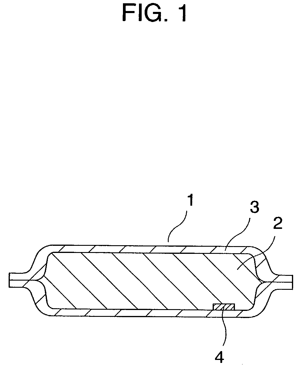
[0030]FIG. 1 is a sectional view of a vacuum heat insulator in accordance with an exemplary embodiment of the present invention. Vacuum heat insulator 1 comprises core 2, enveloping member 3, and adsorbent 4.

[0031]One side of the enveloping member 3 is made of a four-layer laminated film. An outermost layer of the laminated film is a polyamide layer (16 μm in thickness) as a surface protection layer and an inner layer of the laminated film is a polyethylene terephthalate layer (12 μm in thickness). Enveloping member 3 further has an aluminum foil (6 μm in thickness) as an intermediate layer, and a high-density polyethylene layer (50 μm in thickness) for heat-sealing.

[0032]Another side of the enveloping member 3 is made of a four-layer laminated film comprising surface protection layers of a polyamide layer (16 μm in thickness) and a polyethylene terephthalate layer (12 μm in thickness), an intermediate film layer made of an ethylene-vinyl alcohol copolymer resin composite film (15 μ...

second embodiment

[0065]FIG. 6 is a perspective view of a refrigerator in accordance with a second embodiment of the present invention. Refrigerator 5 of the present embodiment uses, as heat insulator 1, the vacuum heat insulator described in the first embodiment. The refrigerator 5 has a freezer compartment 6 at a bottom and a machine room 7 at a back bottom portion. A refrigerant piping 8 is attached to outer box 9 with aluminum tapes. A rigid urethane foam (not shown) using cyclopentane as a foaming agent is filled in a space between an inner box (not shown) and outer box 9. On both side faces of the freezer compartment 6 of the refrigerator 5, vacuum heat insulator 1 produced in accordance with the first embodiment is provided. Between the vacuum heat insulator 1 on the sidefaces of the freezer compartment 6 and outer box 9, to which the vacuum heat insulator is to be attached, the high-temperature refrigerant piping 8 is provided. Moreover, the heat insulator 1 is shaped to substantially cover t...

third embodiment

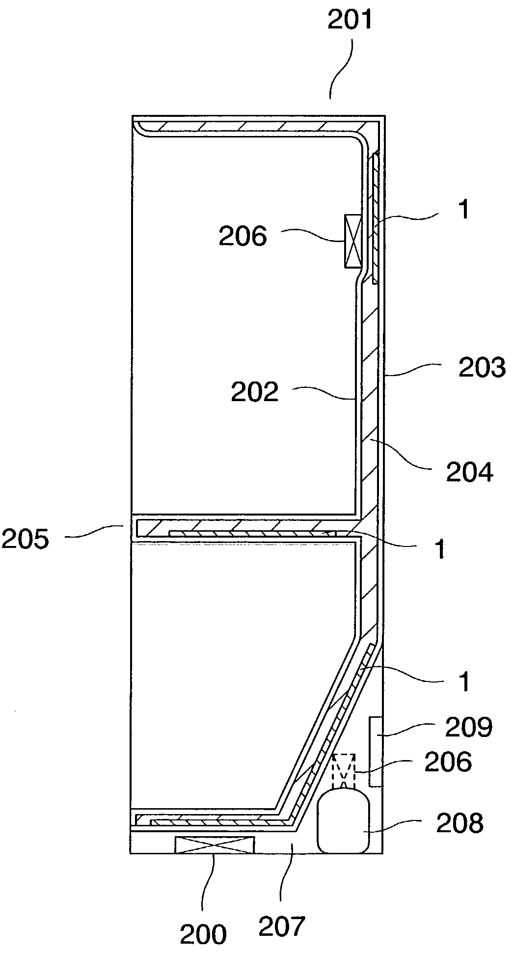
[0069]FIG. 7 is a sectional view of a heat insulation box 101 in accordance with a third embodiment of the present invention. The heat insulation box 101 forming a refrigerator uses vacuum heat insulator 1 of the first embodiment. The heat insulation box 101 comprises an inner box 102 of a vacuum-molded ABS resin, an outer box 103 of a press-molded iron sheet, and a flange 104. To form the heat insulation box 101, the vacuum heat insulator 1 is provided inside of the outer box 103 beforehand, and then urethane resin is filled into a space between the inner box and outer box and foamed so as to surround the vacuum heat insulator 1 with rigid urethane foam 106.

[0070]FIG. 8 is a schematic view of the heat insulation box 101. A top wall of the heat insulation box is provided with one sheet of the vacuum heat insulator 1, as are a back wall and each of two side walls. According to a shape of the heat insulation box 101, the sheet of vacuum heat insulator 1 used for each side wall is cut ...


PUM

PropertyMeasurementUnit
diameteraaaaaaaaaa
thicknessaaaaaaaaaa
thicknessaaaaaaaaaa

Abstract

By using a core made of laminated sheets of inorganic fibers having a particular shape and composition as part of a vacuum heat insulator for a heat insulation box, a heat insulation box excellent in long-term heat insulating properties and productivity can be provided. The vacuum heat insulator can be shaped easily. Therefore, a vacuum heat insulator suitable for a required heat insulation portion can be produced easily and applied to a heat insulation box. This property can increase coverage of the vacuum heat insulator on the heat insulation box, thus improving heat insulating properties of the heat insulation box. This can improve heat insulating properties and productivity of a refrigerator, thermal storage box, cold storage box, or vending machine, and contribute to energy savings.

Description

FIELD OF THE INVENTION[0001]The present invention relates to a heat insulation box that can be used for an apparatus, such as a refrigerator, thermal storage box, cold storage box, vending machine, or water heater. It also relates to a vacuum heat insulator used for these apparatus and to structure of the vacuum heat insulator.BACKGROUND OF THE INVENTION[0002]Energy saving in electric appliances is an unavoidable important problem that has been addressed in recent years. Also, in a heat insulation box used for a refrigerator and other various kinds of electric appliances, improvement in performance of a heat insulator is becoming essential. On the other hand, positive efforts to conserve terrestrial environment is becoming important. One of urgent requests with regard to electric appliances is energy saving; thus, improving heat insulating properties of heat-related electric apparatus is becoming an important problem to address.[0003]One heat insulator that has been recently develop...

Claims


Application Information

Patent Timeline
Patent Type & Authority Patents(United States)
IPC IPC(8): F25D11/00F25D23/00B65D81/18B65D81/38C03C13/00F16L59/065F25D23/06
CPCB65D81/18B65D81/3823B65D81/3897C03C13/00F16L59/065F25D23/062F25D2201/124F25D2201/126F25D2201/14F25D2400/04F25D23/06
Inventor TANIMOTO, YASUAKIHIRAI, CHIE
Owner PANASONIC CORP
Why Eureka
Try Eureka