Mass spectrometer

a mass spectrometer and cyclotron technology, applied in mass spectrometers, instruments, separation processes, etc., can solve problems such as the effect of reducing resolution, minimizing the spread of kinetic energy of injected ions, and minimizing the unforeseen or non-deterministic widening of energy distribution

Active Publication Date: 2007-05-01
THERMO FINNIGAN
View PDF11 Cites 17 Cited by
  • Summary
  • Abstract
  • Description
  • Claims
  • Application Information

AI Technical Summary

Benefits of technology

[0040](j) Minimization of kinetic energy spread of injected ions by cooling in a static or dynamic ion trap, by proper selection and timing of injection potentials, and/or by precise machining of the ion guide syst

Problems solved by technology

It is known to those skilled in the art that the pressure in a vacuum chamber which contains a measurement cell must be as low a

Method used


Image

  • Mass spectrometer
  • Mass spectrometer
  • Mass spectrometer

Examples


Embodiment Construction

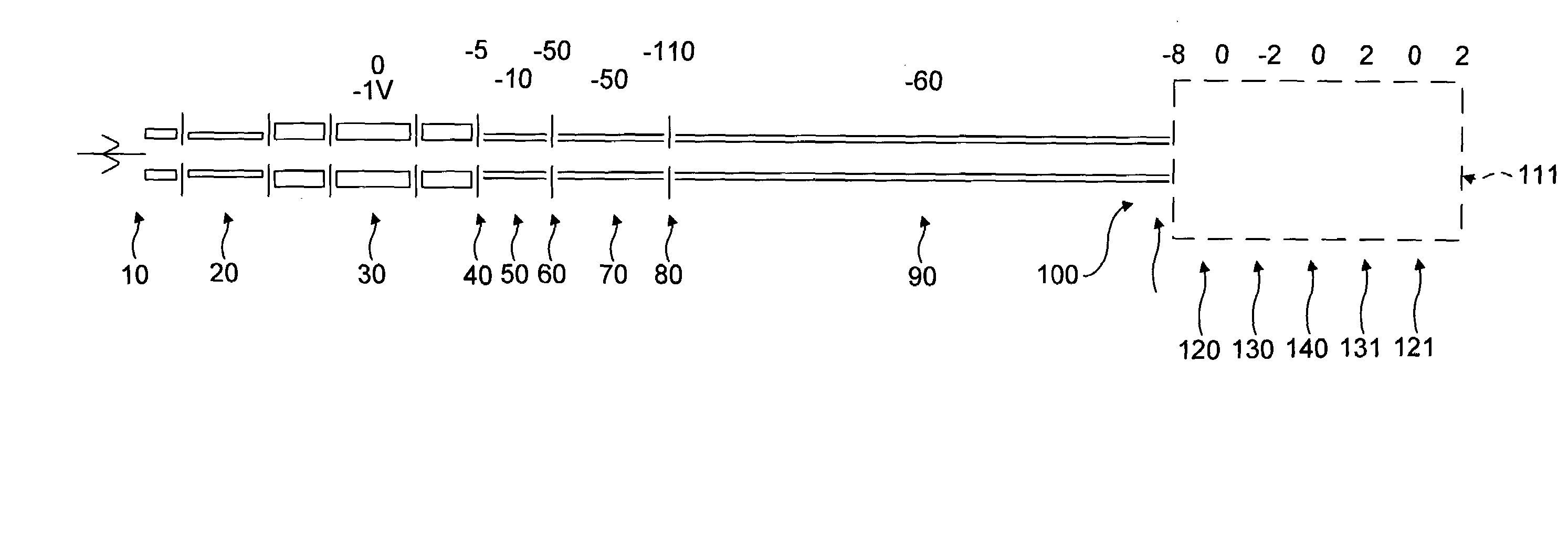
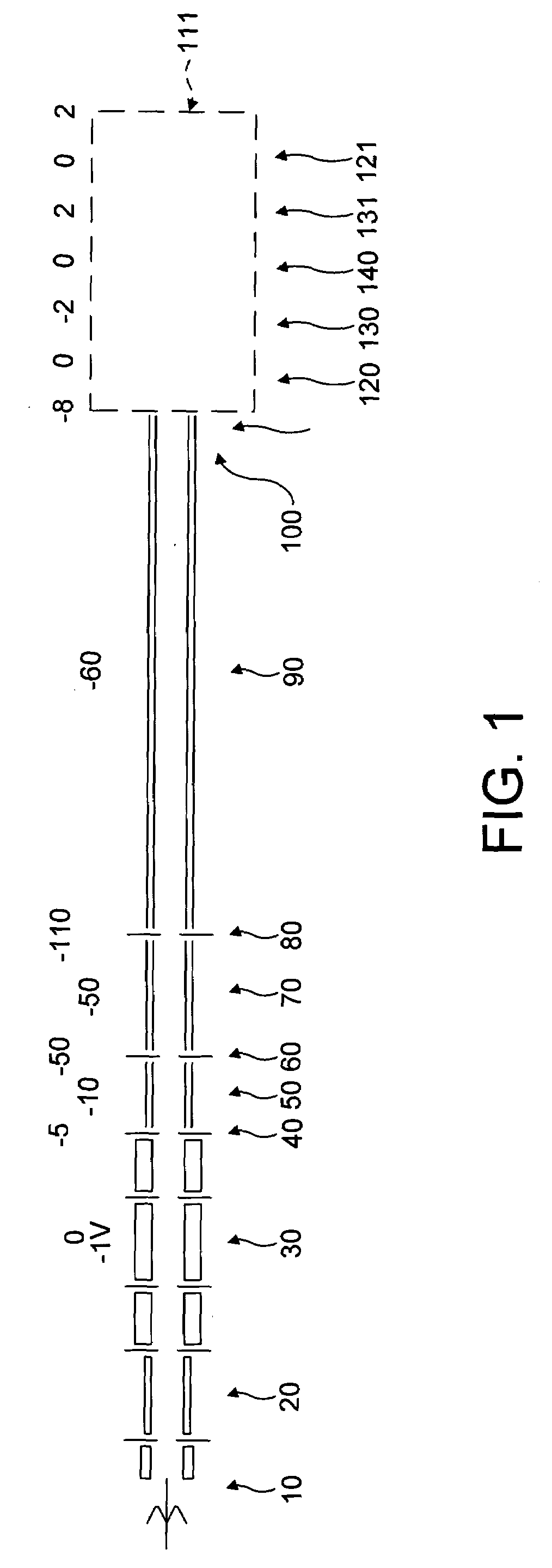
[0055]Referring first to FIG. 1, a highly schematic arrangement of a mass spectrometer system embodying the present invention is shown.

[0056]Ions are generated in an ion source 10, which may be an electrospray ion source (ESI), matrix-assisted laser ion desorption ionisation (MALDI) source, or the like. In preference, the ion source is at atmospheric pressure.

[0057]Ions generated at the ion source are transmitted through a system of ion optics such as one or more multipoles 20 with differential pumping. Differential pumping arrangements to transfer ions from atmospheric pressure down to a relatively low pressure are well known as such in the art and will not be described further.

[0058]Ions exiting the multipole ion optics 20 enter an ion trap 30. The ion trap may be a 2-D or 3-D RF trap, a multipole trap or any other suitable ion storage device, including static electromagnetic or optical traps.

[0059]Ions are ejected from the ion trap 30 through a first lens 40 into a first multipol...


PUM


Abstract

An improved FT-ICR Mass Spectrometer has an ion source 10 which generates ions that are transmitted through a series of multipoles 20 to an ion trap 30. Ions are ejected from the trap 30, through a series of lens and multipolar ion guide stages 40–90, and into a measurement cell 100 via an exit/gate lens 110. The measurement cell is mounted in a vacuum chamber 240 and this assembly is slideably moveable into a bore of a superconducting magnet 400 which provides the magnetic filed to cause cyclotron motion of the generated ions in the cell 100. By minimising the distance between the source 10 and cell 100, and by careful alignment of the ion optics, the ions can travel at high energies right up to the front of the measurement cell 100.
The cell 100 extends in the longitudinal direction of the magnet bore and is coaxial with that. The ratio of the sectional area of the magnet bore to the sectional area of the cell volume is small (less than 3). The magnet is asymmetric and is relatively short on the ion injection side. The cell 100 is supported from in front of the cell and electrical contact is from the rear thereof.

Description

PRIOR APPLICATIONS[0001]This application claims priority from Great Britain Application Number 0305420.2, filed Mar. 10, 2003, entitled Mass Spectrometer.FIELD OF THE INVENTION[0002]The present invention relates to a mass spectrometer and more particularly to a Fourier Transform Ion Cyclotron Resonance Mass Spectrometer.BACKGROUND OF THE INVENTION[0003]High resolution mass spectrometry is widely used in the detection and identification of molecular structures and the study of chemical and physical processes. A variety of different techniques are known for the generation of a mass spectrum using various trapping and detection methods.[0004]One such technique is Fourier Transform Ion Cyclotron Resonance (FT-ICR). FT-ICR uses the principle of a cyclotron, wherein a high frequency voltage excites ions to move in a spiral within an ICR cell. The ions in the cell orbit as coherent bunches along the same radial paths but at different frequencies. The frequency of the circular motion (the c...

Claims


Application Information

Patent Timeline
IPC IPC(8): H01J49/38H01J49/26H01J49/42
CPCH01J49/063H01J49/38
Inventor MALEK, ROBERTMEYER, KAI JURGENSEEDORF, SILKEHORNING, STEVAN ROY
Owner THERMO FINNIGAN
Why Eureka
Try Eureka